Method for calibrating a piezoelectric actuating drive

a technology of piezoelectric actuating drive and actuating drive, which is applied in the field of piezoelectric/electrostrictive device details, piezoelectric/electrostrictive/magnetostrictive devices, piezoelectric/electrostriction/magnetostriction machines, etc., and can solve the problem of precise stroke resolution or transformation, mechanical load, and/or instability effects

Inactive Publication Date: 2002-01-22
DAIMLER AG
View PDF11 Cites 23 Cited by
  • Summary
  • Abstract
  • Description
  • Claims
  • Application Information

AI Technical Summary

Benefits of technology

The use of the piezoelectric effect according to the invention is based on the coupling of mechanical and electric properties by such an effect. A change of mechanical marginal or limiting conditions has effects that can be evaluated. One extreme condition is, for example, a locking of the piezoelectric actuator when it strikes a rigid limit stop. Another extreme condition that can be evaluated is an unhindered longitudinal displacement of the actuator. These conditions have an electric effect in such a way that, in the case of locking,

Problems solved by technology

The precise stroke resolution or transformation (stroke as a function of signal size) of stroke or displacement causing piezoelectric actuating drives is impaired if environmental o

Method used


Image

  • Method for calibrating a piezoelectric actuating drive
  • Method for calibrating a piezoelectric actuating drive
  • Method for calibrating a piezoelectric actuating drive

Examples


Embodiment Construction

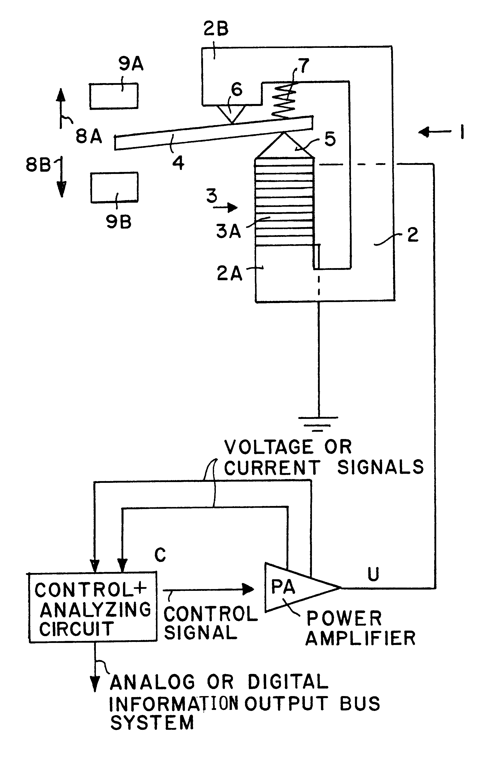
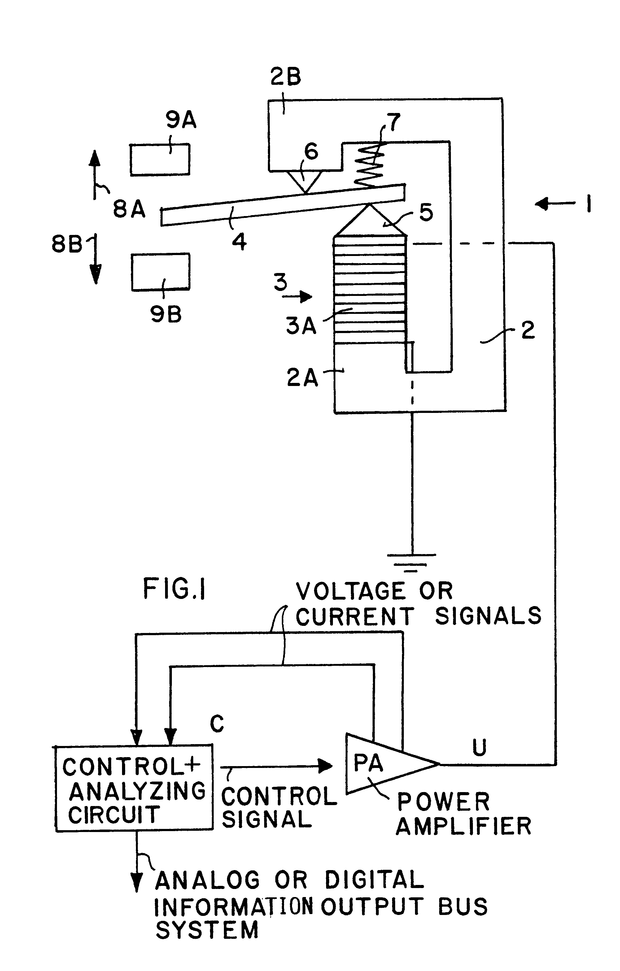
The piezoelectric actuator 1, as shown in FIG. 1, comprises a carrier frame 2, a stack 3 of piezoelectric elements 3A and an actuator output 4 formed as a beam. The stack 3 is secured with one end to a support 2A formed by the frame 2. The actuator output beam 4 is hinged between a free end 5 of the piezostack 3 and a knife-edge bearing 6. This bearing 6 is formed in a frame extension 2B laterally displaced relative to the free end 5. The output beam 4 is held against the bearing 6 and against the free end 5, preferably also formed as an edge, by a pressure spring 7. The knife-edge bearing 6 is fixed rigidly in the carrier frame.

The stack 3 of piezoelectric elements 3A is energized by an energizing signal U provided by a power amplifier PA under the control of a control and analyzing circuit C which receives feedback signals from the amplifier PA and provides respective control signals to the amplifier PA. The circuit C also provides digital or analog output signals for further use....


PUM


Abstract

A piezoelectric actuating drive is calibrated so that displacements or movements of its actuator output beam (4) become independent of environmental operating conditions and of piezoelectric instabilities. For this purpose an automatic determination and correlating of energizing signal values and respective displacement positions of an actuator beam (4) are performed on the basis of first sensing or measuring striking times (t1, t2) when the actuator beam (4) encounters at least one, preferably two limit stops which limit the beam displacement caused by piezoelectric action. The change of the electric capacitance of a piezostack (3) that displaces the actuator output beam (4) is measured when the beam (4) strikes a limit stop. Instead of measuring a change in the electric capacitance of the piezostack (3), electric charge impulses may be measured at the time (t1, t2) and evaluated for the correlation between the energizing control or input signal and the corresponding output beam displacement. The correlation or calibration is performed automatically by an electronic signal processing circuit when such calibration is desired in response to an operator input or it is performed automatically in response to a control program stored in a memory of the electronic signal processing circuit.

Description

The invention concerns a method for calibrating a piezoelectric actuating drive which includes an electronic circuit for energizing a stack of piezoelectric elements which perform a displacement according to the piezoelectric effect in response to an energizing signal.BACKGROUND INFORMATIONA piezoelectric actuating drive is known from German Patent Publication DE-AS 43 03 125 comprising control electronics and a piezoelectric actuator. The known drive includes a circuit arrangement which improves the correlation of the piezoelectric positioning movement or displacement with the electric voltage of an energizing signal applied to a piezoelectric member. The conventional correlation wants to make sure that particularly influences on the piezoelectric displacement due to hysteresis are reduced. For this purpose a second actuating drive is provided, the output signal of which is linearly linked or coordinated with the positioning movement or displacement of the first actuating drive.The...

Claims


Application Information

Patent Timeline
IPC IPC(8): H01L41/00H01L41/04H01L41/09G05D3/10H02N2/04
CPCH01L41/042H02N2/062H02N2/043H10N30/802
Inventor JAENKER, PETER
Owner DAIMLER AG
Why Eureka
Try Eureka