Illumination corrections to reduce geometrical artifacts in seismic data

a technology of seismic data and geometric artifacts, applied in the field of three-dimensional (3d) seismic prospecting, can solve problems such as obscuring the true geologic picture, affecting the accuracy of seismic data acquisition, so as to eliminate the discontinuity of the weighting function

Inactive Publication Date: 2002-01-29
EXXONMOBIL UPSTREAM RES CO
View PDF1 Cites 62 Cited by
  • Summary
  • Abstract
  • Description
  • Claims
  • Application Information

AI Technical Summary

Problems solved by technology

The reflections are caused by differences in elastic properties, specifically wave velocity and rock density, which lead to differences in impedance at the interfaces.
Examples of non-geologic amplitude effects that can be particularly troublesome are source and receiver variations, coherent noises, electrical noise or spikes, and overburden and transmission effects.
If uncorrected, these effects can distort the seismic image and obscure the true geologic picture.
In reality, midpoint distribution is not always uniform.
For example, in marine acquisition there may be gaps due for example to physical obstructions such as platforms.
On land, physical obstacles to seismic acquisition are often plentiful and various.
Such irregularities in midpoint distribution and / or azimuth variation generally lead to non-uniform illumination of reflectors and irregularities in the measured seismic amplitudes.
All such non-uniform illumination is either not compensated for in present methods of controlled amplitude migration, or is inadequately compensated for as described below.
Consequently, prestack 3-D migrated images are often contaminated with non-geologic artifacts called geometrical effects or "acquisition footprints".
Unless properly compensated for in the stacking process, the incorrect change of amplitude and signal / noise resulting from these artifacts can interfere with the ultimate interpretation of seismic images and attribute maps.
A basic difficulty with this approach is its inability to deal with gaps more than a bin width in size.
This method is computationally expensive for routine application to 3-D data and does not account for varying azimuths typical of multi-cable marine acquisition.
As noted by the inventors (ref: 62.sup.nd Annual SEG Meeting Extended Abstracts pp 970-973 (1992)), this method encounters difficulties with wide azimuth acquisition.
In addition, EQDMO is unable to handle large data gaps, and because the method lacks a true wave theoretical basis, it is unable to guarantee that a uniformly reflective reflector will be correctly imaged.

Method used


Image

  • Illumination corrections to reduce geometrical artifacts in seismic data
  • Illumination corrections to reduce geometrical artifacts in seismic data

Examples


Embodiment Construction

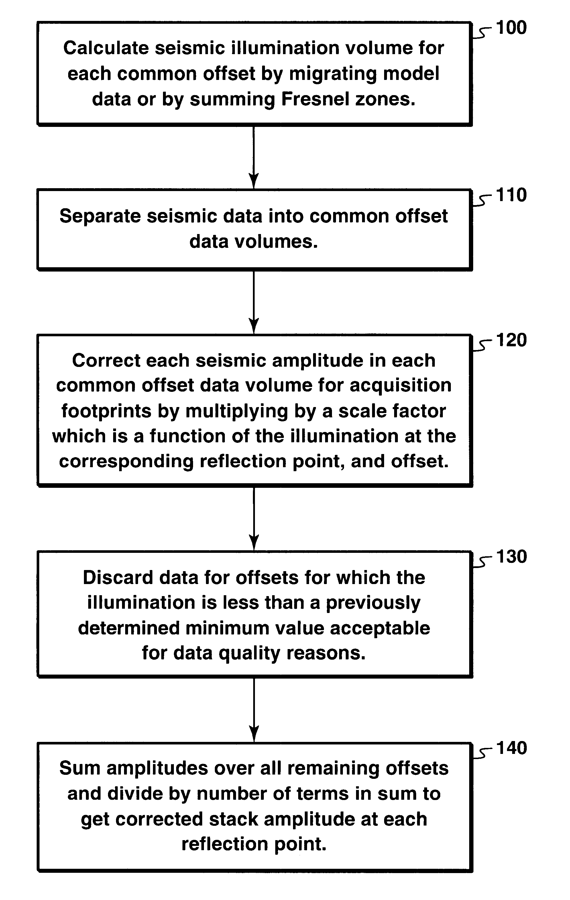
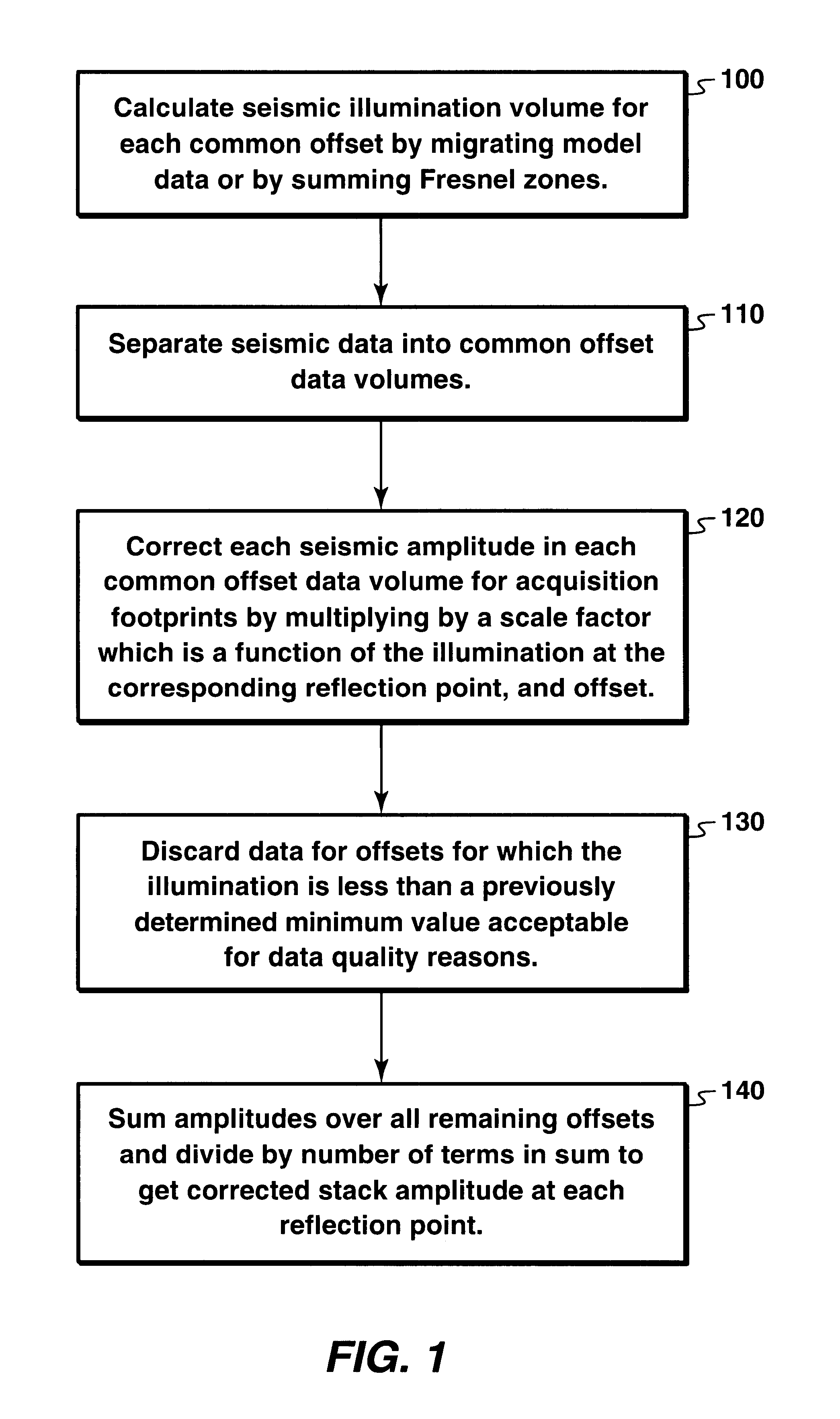
As stated above, reflector illumination is defined to be the imaged amplitude achieved by the given acquisition geometry when the reflection coefficient on the reflector of interest is unity everywhere. This can be computed by constructing and migrating model data, a procedure that will be obvious to anyone skilled in the art of seismic migration. Alternatively, the illumination can be computed (with superior computational efficiency) by summing Fresnel zones on the reflector surface. In the case of a dipping reflector, the illumination function depends on the magnitude of the dip, which must be determined in advance.

The method of constructing and migrating model data is based on the premise that the seismic data will give a good indication of the depth and horizontal extent of any reflector of interest. From that information, one can construct a computer model, including the acquisition geometry and the reflector, and compute imaged amplitudes as a function of offset and reflection...


PUM


Abstract

A method for correcting seismic amplitudes for geometrical artifacts resulting in non-uniform illumination of reflector surfaces. The illumination is calculated for each offset as a function of spatial position. The amplitudes are scaled by a scale factor which may be the reciprocal of the illumination. Data considered to be poor quality due to low illumination may be discarded, and the amplitudes scaled further to compensate for the discarded data.

Description

FIELD OF THE INVENTIONThis invention relates generally to the field of three-dimensional (3-D) seismic prospecting. More particularly, the invention relates to a method for correcting errors in seismic amplitudes created by acquisition geometry.BACKGROUND OF THE INVENTIONIn the oil and gas industry, seismic prospecting techniques are commonly used to aid in the search for and evaluation of hydrocarbon deposits located in subterranean formations. In seismic prospecting, seismic energy sources are used to generate a seismic signal which propagates into the earth and is at least partially reflected by subsurface seismic reflectors. Such seismic reflectors typically are interfaces between subterranean formations having different elastic properties. The reflections are caused by differences in elastic properties, specifically wave velocity and rock density, which lead to differences in impedance at the interfaces. The reflections are recorded by seismic detectors at or near the surface o...

Claims


Application Information

Patent Timeline
Patent Type & Authority Patents(United States)
IPC IPC(8): G01V1/28
CPCG01V1/28
Inventor WINBOW, GRAHAM A.ALLDRIDGE, JAMES R.WAHRMUND, LESLIE A.
Owner EXXONMOBIL UPSTREAM RES CO
Why Eureka
Try Eureka