Apparatus for controlling temperature of fluid by use of thermoelectric device

a technology of thermoelectric device and fluid, which is applied in the direction of lighting and heating apparatus, machines using electric/magnetic effects, refrigerating machines, etc. it can solve the problems of destroying the ozone layer caused by the constant release into the atmosphere of chlorofluorocarbons (cfcs), and the thermo-module 1 is often broken by the thermal stress

Inactive Publication Date: 2002-02-12
CSE INC
View PDF12 Cites 26 Cited by
  • Summary
  • Abstract
  • Description
  • Claims
  • Application Information

AI Technical Summary

Problems solved by technology

The destruction of the ozone layer caused by the constant release into the atmosphere of chemicals known as chlorofluorocarbons (CFCs) is a serious problem for the global environment.
Since the temperature control unit rigidly held by use of the bolts 41S and the nuts 42S can not release the thermal stress, there is a problem that the thermo-modules 1S are often broken by the thermal stress.

Method used


Image

  • Apparatus for controlling temperature of fluid by use of thermoelectric device
  • Apparatus for controlling temperature of fluid by use of thermoelectric device
  • Apparatus for controlling temperature of fluid by use of thermoelectric device

Examples


first embodiment

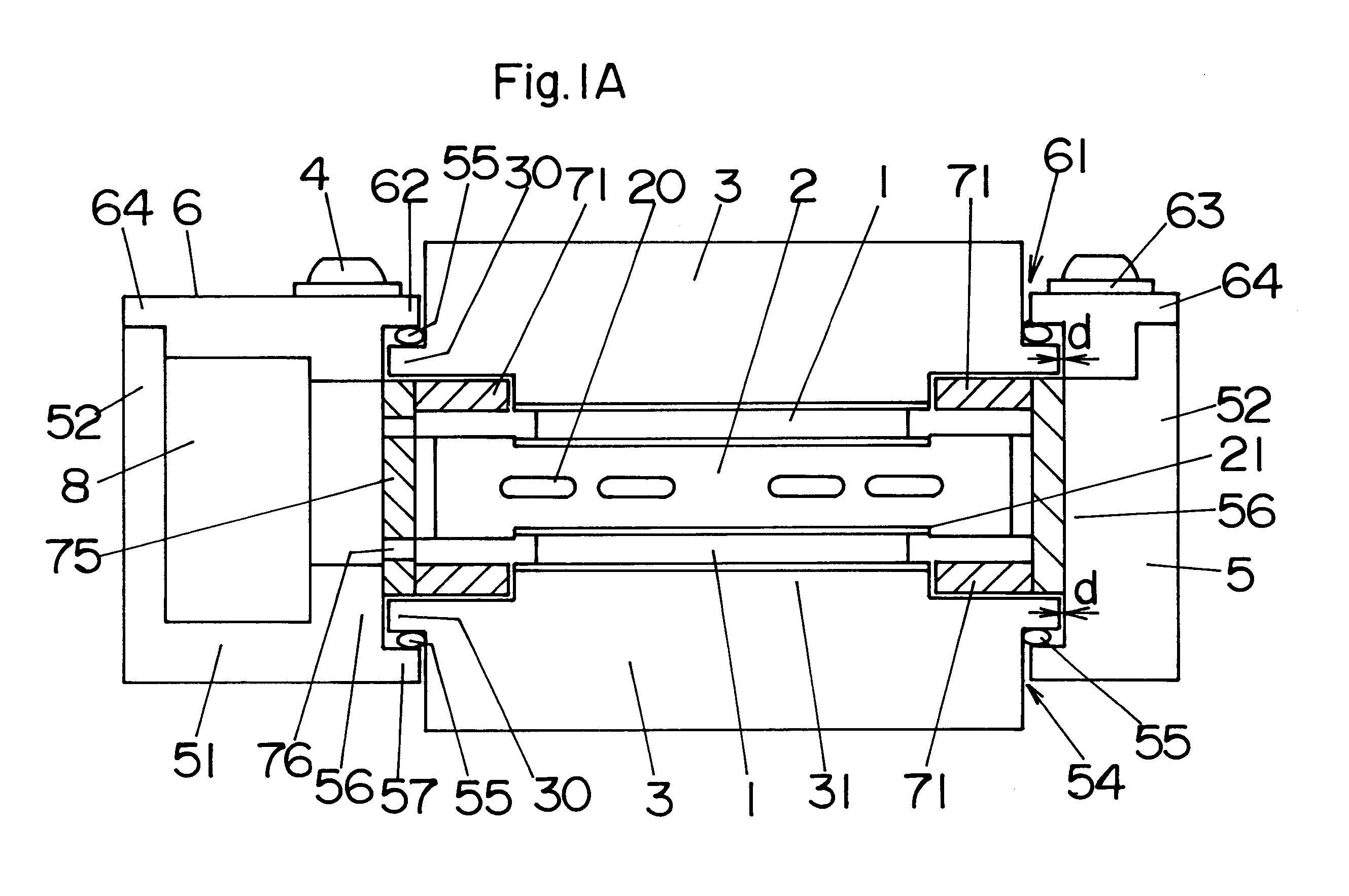
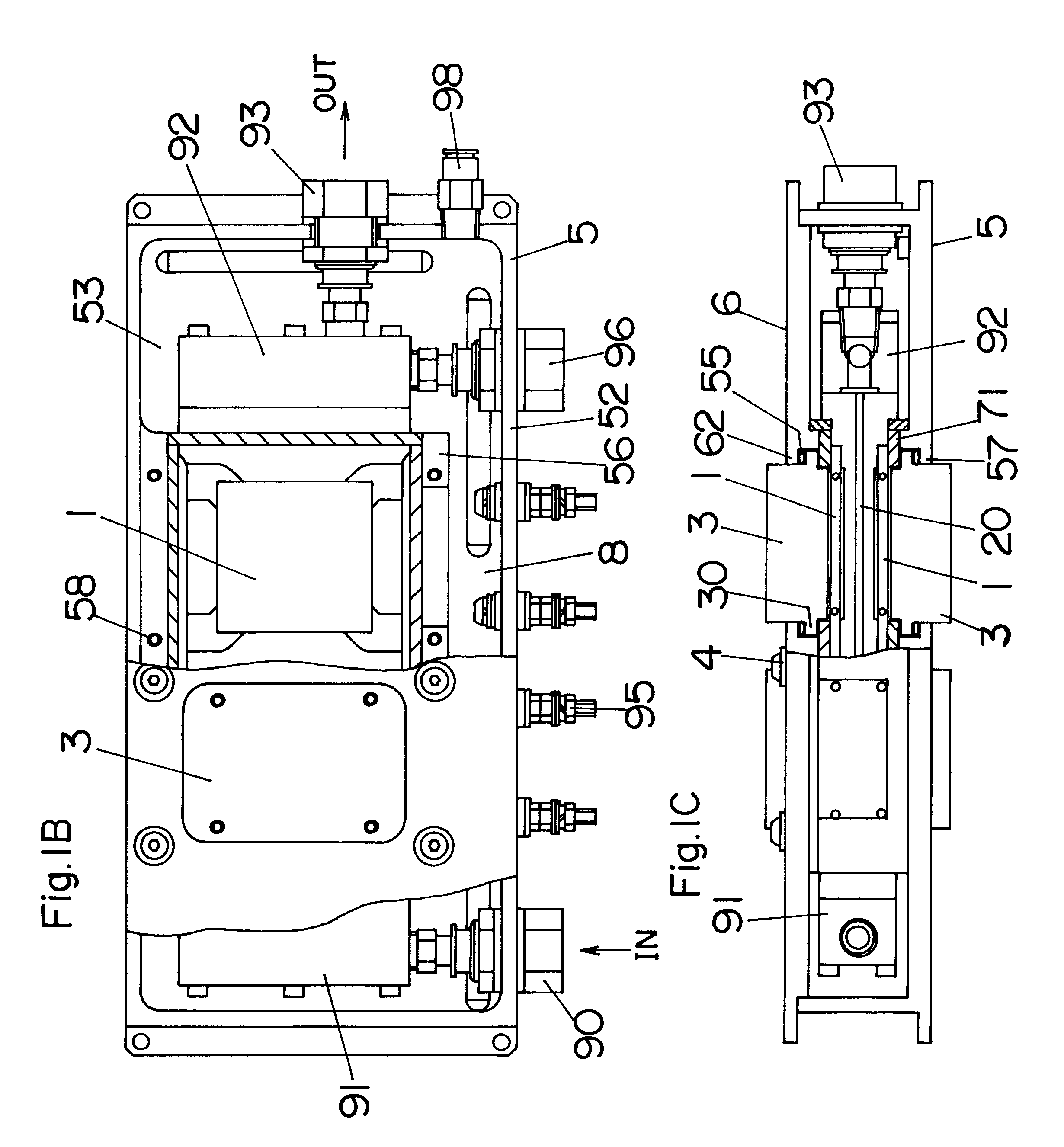
As shown in FIGS. 1A to 1C, an apparatus for controlling the temperature of a fluid according to a first embodiment of the present invention has two temperature control units in series. Each of the temperature control units comprises a first heat-transfer member 2 having channels 20, through which the fluid flows, a pair of thermo-modules 1 each incorporating a thermoelectric device that is often called Peltier device, and a pair of second heat-transfer members 3 for transferring heat radiated from the thermo-modules 1.

The thermo-module 1 has a structure that N-type and P-type semiconductors are arranged between upper and lower electrodes 10, 11, as shown in FIG. 2, and ceramic plates 15, 16 are placed on the upper and lower electrodes, respectively. Since the principle of the thermo-module has been previously known, its detail explanation is omitted. In brief, when a direct current is supplied to the thermo-module 1 through a lead wire 13, as shown in FIG. 2, it flows from the N-ty...

second embodiment

As shown in FIGS. 6A to 6C, an apparatus for controlling the temperature of a fluid according to a second embodiment of the present invention has four temperature control units in series. Each of the temperature control units is composed of a first heat-transfer member 2A having channels 20A, through which the fluid flows, a single thermo-module 1A incorporating a thermoelectric device that is often called Peltier device, and a single second heat-transfer member 3A for transferring heat radiated from the thermo-modules 1A. In the temperature control unit of the first embodiment, the two thermo-modules 1 are disposed on the opposite surfaces of the first heat-transfer member 2. In this embodiment, the thermo-module 1A is disposed on only one side of the first heat-transfer member 2A. As the thermo-module 1A and the second heat-transfer member 3A, it is possible to use those used in the first embodiment.

As shown in FIGS. 6B and 6C, the first heat-transfer members 2A of the four temper...

third embodiment

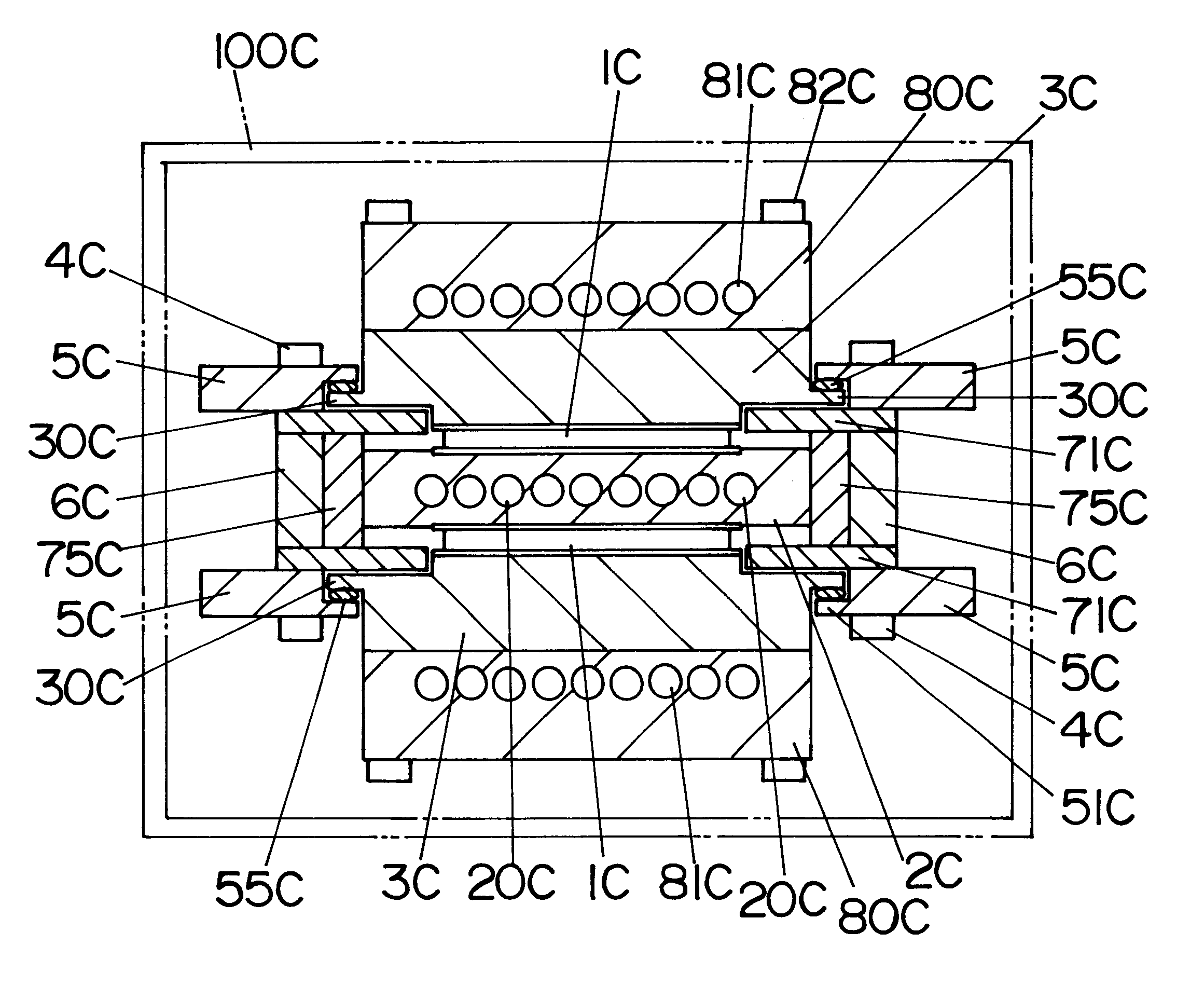
As shown in FIGS. 8A to 8C, an apparatus for controlling the temperature of a fluid according to a third embodiment of the present invention has a plurality of temperature control units in series. Each of the temperature control units is substantially the same structure as that of the first embodiment. Therefore, no duplicate explanation to common parts is deemed necessary. The apparatus of this embodiment uses a pair of upper and lower holding frames 5C, coupling member 6C having screw holes 62C, and a sidewall member 7C extending around the temperature control unit and between the holding frames. Each of the holding frames 5C is formed with an aperture 54C, first flange 51C, and a second flange 52C. The numeral 53C designates a screw-hole for the use of a bolt 4C. The coupling member 6C is disposed between the holding frames 5C.

The first flange 51C of the upper holding frame 5C is pressed against a flange 30C of the upper one of second heat-transfer members 3C through a sealing ma...


PUM


Abstract

An apparatus for controlling the temperature of a fluid by use of a thermoelectric device comprises at least one temperature control unit, which is composed of a first heat-transfer member having at least one channel, through which the fluid flows, a pair of thermo-modules each incorporating the thermoelectric device, which are placed on opposite surfaces of the first heat-transfer member, and a pair of second heat-transfer members, each of which has a flange on its periphery and is placed on the thermo-module. The temperature control unit is stably held between a pair of holding frames each having an aperture such that each of the holding frames is pressed against the flange of the second heat-transfer member through a sealing material having elasticity, and a part of the second heat-transfer member is exposed through the aperture. This apparatus is capable of cooling the fluid without chlorofluorocarbons (CFCs) used as a coolant for conventional refrigerators.

Description

1. Field of the InventionThe present invention relates to an apparatus for controlling the temperature of a fluid by use of a thermoelectric device that is often called Peltier device.2. Disclosure of the Prior ArtThe destruction of the ozone layer caused by the constant release into the atmosphere of chemicals known as chlorofluorocarbons (CFCs) is a serious problem for the global environment. For example, the CFCs are used as a coolant for conventional refrigerators. From the viewpoint of the global environmental protection, development is going on to fine an alternative to the conventional refrigerators using the CFCs. In recent years, a cooling apparatus using a thermoelectric device that is often called Peltier device has gained attention.FIG. 16 shows a schematic cross-sectional view of a conventional apparatus for controlling the temperature of a fluid by use of the thermoelectric device. This apparatus comprises a temperature control unit, which is composed of a first heat-t...

Claims


Application Information

Patent Timeline
Patent Type & Authority Patents(United States)
IPC IPC(8): F25B21/04F25B21/02H01L35/28H01L35/30
CPCH01L35/30F25B21/04H10N10/13
Inventor KONTANI, TATSUOAOKI, KANTARO
Owner CSE INC
Why Eureka
Try Eureka