
Ultrasound imaging method and apparatus based on pulse compression technique using modified golay codes

a pulse compression and ultrasonic imaging technology, applied in the field of ultrasonic imaging system, can solve the problems of short pulse imaging system not obtaining information for a target object inside the body from which short pulses are reflected, power of received signal cannot be increased in this way, and undesirable frequency characteristics of golay codes. a wider frequency spectrum

Inactive Publication Date: 2002-02-26
MEDISON CO LTD +1
View PDF3 Cites 71 Cited by
  • Summary
  • Abstract
  • Description
  • Claims
  • Application Information

AI Technical Summary

Benefits of technology

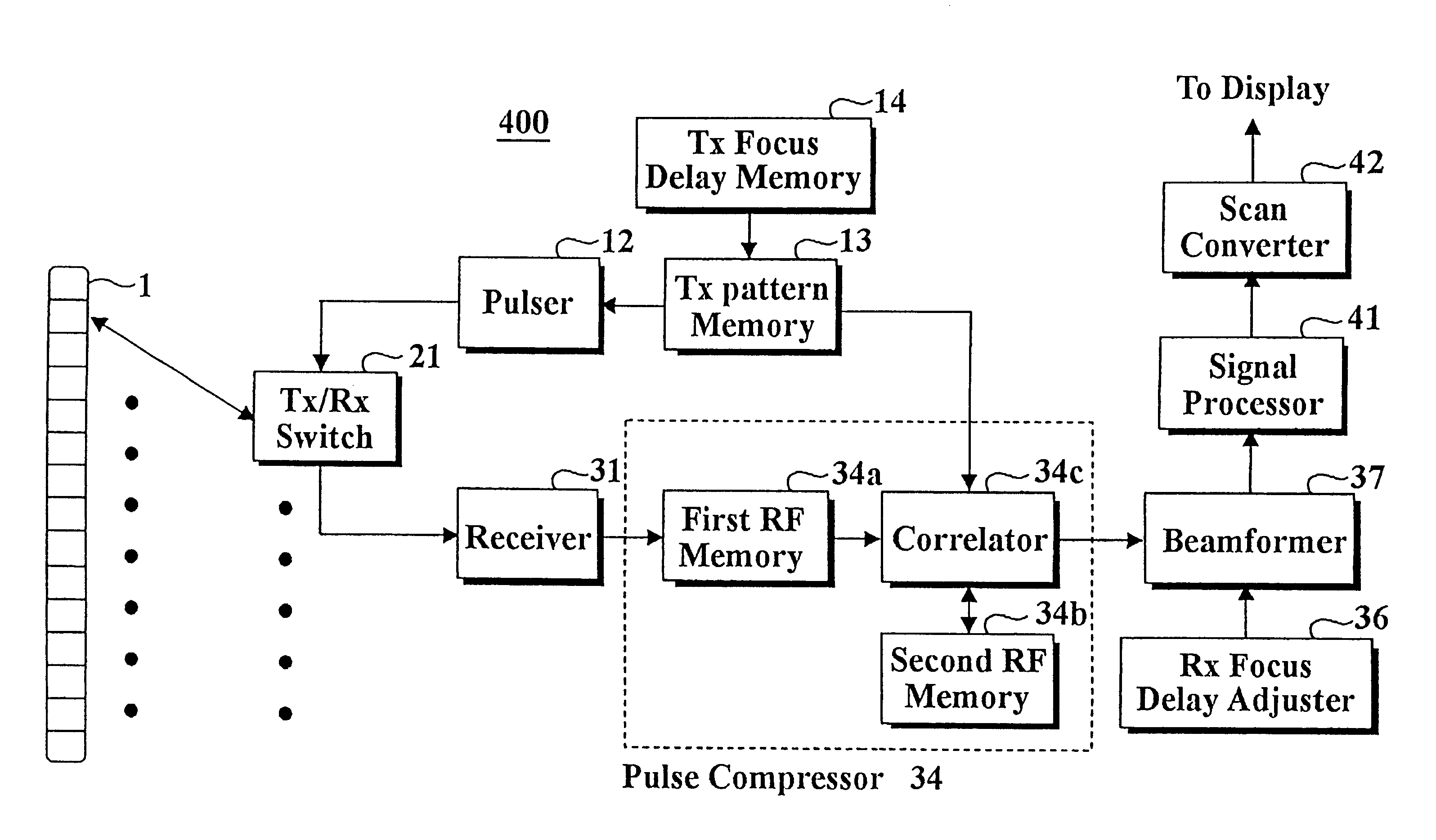
Another objective of the present invention is to provide an imaging apparatus for effectively implementing the ultrasound imaging method using the codes.

Problems solved by technology

Due to the decrease in power of the ultrasound during propagation into highly attenuating medium such as rubber, soft tissue and the like, the short-pulse imaging system may not obtain information for a target object inside the body from which the short pulses are reflected.
Since the medical ultrasound imaging system 100 may cause damage to the body when it increases the peak voltage of the transmitted short pulses, the power of the received signal can not be increased in this way.
However, one of undesirable frequency characteristics of the Golay codes is a wider frequency spectrum than that of the conventional ultrasound transducer.
That is, there is some loss in the power of a Golay code at the ultrasound transducer such that the SNR of the system can not reach a desired level.

Method used


Image

  • Ultrasound imaging method and apparatus based on pulse compression technique using modified golay codes
  • Ultrasound imaging method and apparatus based on pulse compression technique using modified golay codes
  • Ultrasound imaging method and apparatus based on pulse compression technique using modified golay codes

Examples


Embodiment Construction

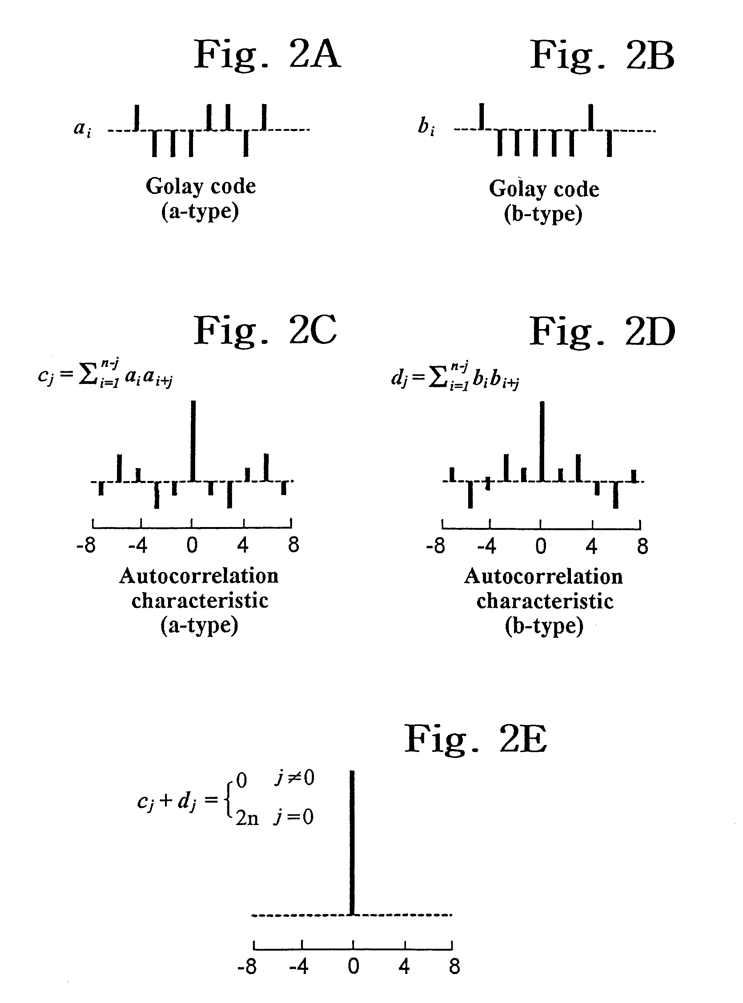
The present invention is characterized with the use of modified Golay codes in the ultrasound transmission. The modified Golay codes used in the present invention consists of a pair of complementary binary sequences of a same length. The autocorrelations of the complementary sequences has a same main lobe and side lobes of a same magnitude but of opposite polarities. Accordingly, the summation of the autocorrelations of the complementary sequences has a main lobe of which magnitude is double that of the main lobe of the autocorrelation of each sequence and has no side lobes.

FIG. 2 represents the characteristics of Golay codes. FIGS. 2A and 2B show a pair of the complementary Golay codes and FIGS. 2C and 2D show the autocorrelations of the complementary Golay codes. And FIG. 2E is the summation of the autocorrelations shown in FIGS. 2C and 2D. In FIG. 2, a.sub.i and b.sub.i represent the binary elements of the complementary codes of a code length, having either +1 or -1. And the auto...


PUM


Abstract

An ultrasound imaging method for forming an image of an object using received signals reflected from the object, received after transmitting an ultrasound pulse to the object. The inventive method comprises the steps of (a) transmitting a first set of the ultrasound pulses to the object by applying voltages according to a first code of a pair of modified Golay codes to one or more transducers; (b) performing pulse compression on a first set of reflected signals of the first set of the ultrasound pulses reflected from the object; (c) transmitting a second set of the ultrasound pulses to the object by applying the voltages according to a second code of the pair of the modified Golay codes to said one or more transducers; (d) performing pulse compression on a second set of reflected signals of the second set of the ultrasound pulses reflected from the object; (e) adding the pulse compressed signals of the first and the second sets of the reflected signals; (f) producing a receive-focused signal by using the added signal; and (g) displaying the image according to the receive-focused signal after signal processing.

Description

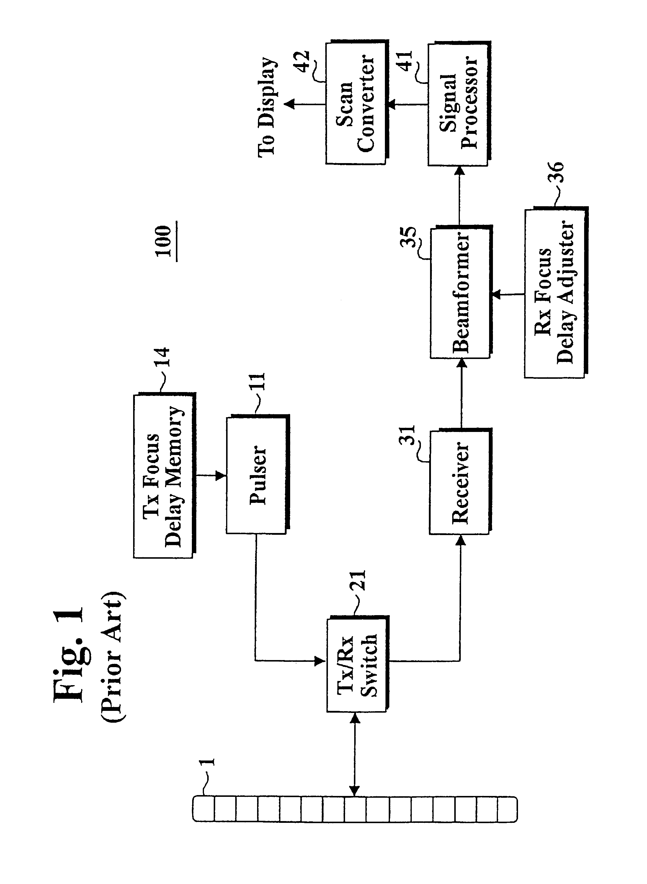
1. Field of the InventionThe present invention relates to an ultrasound imaging system. In particular, the invention relates to an ultrasound imaging system based on a pulse compression technique using modified Golay codes.2. Description of the Related ArtConventionally, a medical ultrasound imaging system obtains information about a human body by transmitting short ultrasound pulses. FIG. 1 shows a block diagram of a conventional short-pulse ultrasound imaging system 100, which comprises a transducer array 1, a pulser 11, a TX(transmission) focus delay memory 14, a TX / RX(receiving) switch 21, a receiver 31, a beamformer 35, an RX focus delay adjuster 36, a signal processor 41 and a scan converter 42.The TX focus delay memory 14 stores a delay pattern of ultrasound pulses to be transmitted into a human body from the transducer array 1. The TX focus delay memory 14 provides a binary sequence corresponding to the delay pattern to the pulser 11.As a method of determining the TX focus d...

Claims


Application Information

Patent Timeline
IPC IPC(8): G01S15/89G01S15/10G01S15/00G01S7/52A61B8/00
CPCG01S15/104G01S15/8961G01S15/8959A61B8/00
Inventor SONG, TAI KYONGYOO, YANG MO
Owner MEDISON CO LTD
Learn More