Filter arrangement; sealing system; and methods

a filter arrangement and sealing system technology, applied in the field of engine air flow system, can solve problems such as substantial damag

Inactive Publication Date: 2002-02-26
DONALDSON CO INC
View PDF40 Cites 540 Cited by
  • Summary
  • Abstract
  • Description
  • Claims
  • Application Information

AI Technical Summary

Benefits of technology

Attention is directed to FIG. 1. FIG. 1 is a perspective view of a first embodiment of a filter pack 50. The preferred filter pack 50 depicted includes filter media 55 and a scaling system 60. In preferred constructions, the filter media 55 is designed to remove particulates from a fluid, such as air, passing through the filter media 55, while the sealing system 60 is designed to seal the filter pack 50 against a sidewall of a housing or duct, as shown in FIGS. 8 and 9. By the term "seal," it is meant that the sealing system 60, under normal conditions, prevents unintended levels of fluid from passing through a region between the filter pack 50 and the sidewall of the housing or duct; i.e., the sealing system 60 inhibits fluid flow from avoiding passage through the filtering media 55 of filter pack 50.
During use of the arrangements depicted, inward forces are exerted around the circumference of the frame 605. Inward forces exerted against the semicircular ends 511, 512 can cause the straight segments 513, 514 to bow or bend. Structure is provided as part of the frame 605 to prevent the straight segments 513, 514 from bowing. While a variety of structures are contemplated herein, in the particular embodiment illustrated in FIG. 12, cross braces 610 are provided to provide structural rigidity and support to the straight segments 513, 514. As can be seen in FIG. 12, the particular cross braces 610 depicted form a truss system 612 between the opposing straight segments 513, 514. The truss system 612 includes a plurality of rigid struts 614, preferably molded as a single piece with the remaining portions of the frame 605.

Problems solved by technology

The particulate material, should it reach the internal workings of the various mechanisms involved, can cause substantial damage thereto.

Method used


Image

  • Filter arrangement; sealing system; and methods
  • Filter arrangement; sealing system; and methods
  • Filter arrangement; sealing system; and methods

Examples


Embodiment Construction

In this section, examples are provided of usable materials. The particular choice for any given material will vary, depending on the filtering application. In other words, the particular material selected for the systems usable herein will be decided upon by the system designer based on the system requirements. A variety of materials are possible. The following section provides examples of materials that have been found to be suitable.

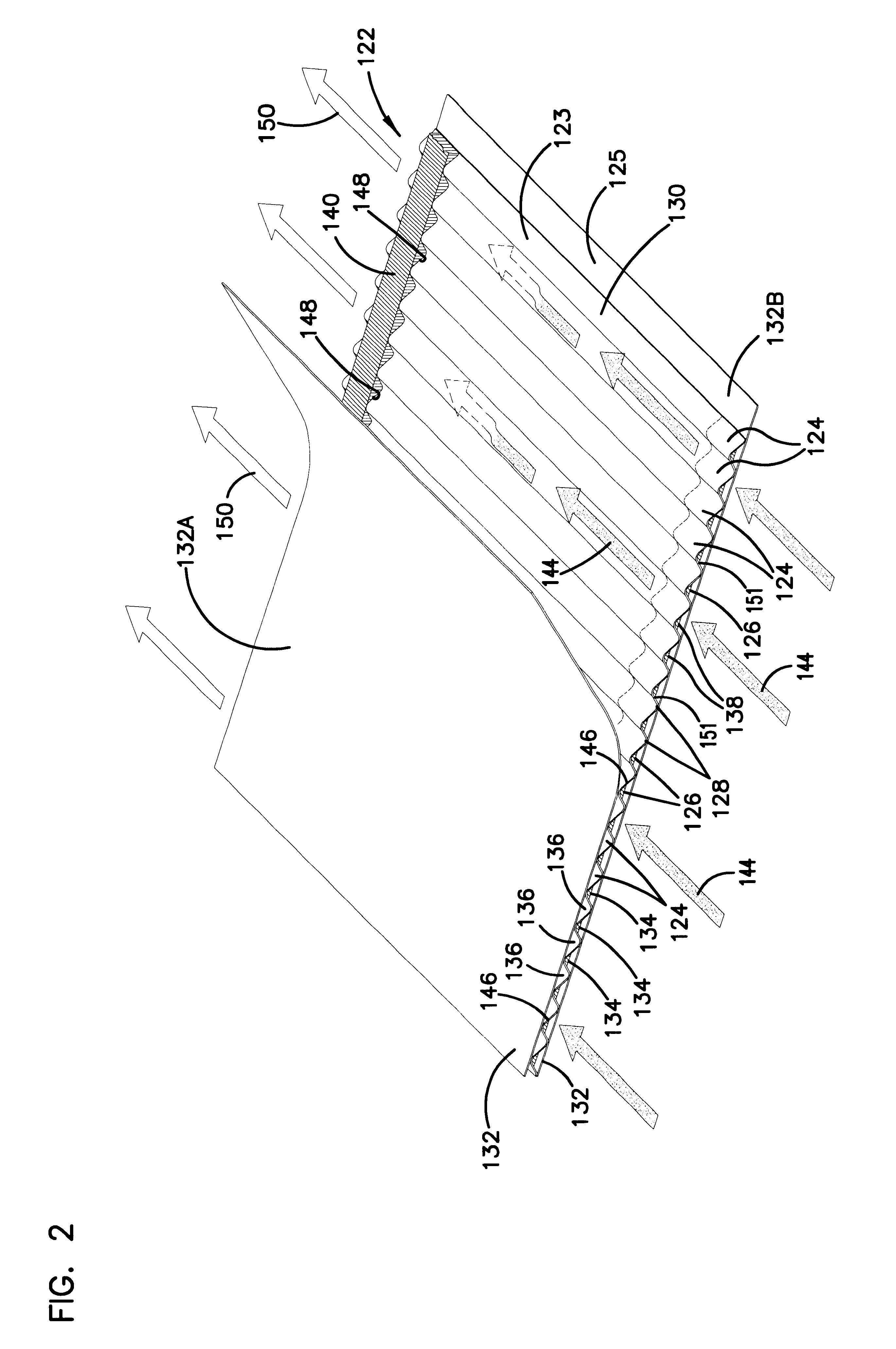
The media 122 can comprise cellulose. One example of media usable in the system described above is as follows: cellulose media with the following properties: a basis weight of about 45-55 lbs. / 3000 ft.sup.2 (84.7 g / m.sup.2), for example, 48-54 lbs. / 3000 ft.sup.2 ; a thickness of about 0.005-0.015 in, for example about 0.010 in. (0.25 mm); frazier permeability of about 20-25 ft / min, for example, about 22 ft / min (6.7 m / min); pore size of about 55-65 microns, for example, about 62 microns; wet tensile strength of at least about 7 lbs / in, for example, 8.5 ...


PUM

PropertyMeasurementUnit
thicknessaaaaaaaaaa
thicknessaaaaaaaaaa
diameteraaaaaaaaaa

Abstract

A filter pack includes a filter construction and a sealing system for sealing the construction within a duct or housing. The filter construction has first and second opposite flow faces and is configured for a straight-through flow. The sealing system includes a frame construction and a compressible seal member. The compressible seal member is molded around a portion of the frame construction. The compressible seal member is sufficiently compressible to form a radial seal between and against the frame construction and a surface of a housing when the filter pack is inserted within the housing.

Description

This disclosure concerns filter constructions for engines and methods of filtering and filter preparation. In particular, the disclosure describes a filter arrangement having a sealing system.Gas streams often carry particulate material therein. In many instances, it is desirable to remove some or all of the particulate material from a gas flow stream. For example, air intake streams to engines for motorized vehicles or power generation equipment, gas streams directed to gas turbines, and air streams to various combustion furnaces, often include particulate material therein. The particulate material, should it reach the internal workings of the various mechanisms involved, can cause substantial damage thereto. It is therefore preferred, for such systems, to remove the particulate material from the gas flow upstream of the engine, turbine, furnace or other equipment involved. A variety of air filter or gas filter arrangements have been developed for particulate removal. In general, h...

Claims


Application Information

Patent Timeline
Patent Type & Authority Patents(United States)
IPC IPC(8): B01D46/52B01D39/16F02M35/024B01D46/00B01D46/10
CPCB01D46/0001B01D46/10B01D46/527B01D2265/028B01D2279/60B01D2271/02B01D2271/027B01D2275/208B01D2267/40Y10S55/30Y02A50/2351B01D27/08B01D25/24B01D46/52B01D46/0002B01D46/62
Inventor GIESEKE, STEVEN SCOTTFINNERTY, CAROLYN J.
Owner DONALDSON CO INC
Why Eureka
Try Eureka