
Elimination of vapour anaesthetics from patients after surgical procedures

a vapour anaesthetic and surgical procedure technology, applied in the field of vapour anaesthetics, to achieve the effect of preventing any perturbation of the arterial pco.sub.2 and facilitating recovery

Inactive Publication Date: 2002-03-12
FISHER JOSEPH A
View PDF5 Cites 54 Cited by
  • Summary
  • Abstract
  • Description
  • Claims
  • Application Information

AI Technical Summary

Benefits of technology

According to one aspect of the invention, there is provided a new breathing circuit and components thereof that can, for example, be added to a standard circle anaesthetic circuit for hastening the recovery of patients administered vapour anaesthetics.
In effect, the device passively, precisely and continuously matches the amount of CO.sub.2 breathed in by the patient to the amount of total breathing, thereby preventing any perturbation of the arterial PCO.sub.2. This is opposed to servo-controllers which are always attempting to compensate for changes. Persons skilled in the art, however, may automate the circuit by using a servo-controller or computer to monitor and deliver the amounts from the reserve gas supply.
According to another aspect of the invention, the new simple breathing circuit is used to treat a patient to enable the patient to recover more quickly from, and to hasten the recovery of the patient after, vapour anaesthetic administration.
According to another aspect of the invention, the use of the said circuit is made to hasten the recovery of patients from vapour anaesthetics administration.
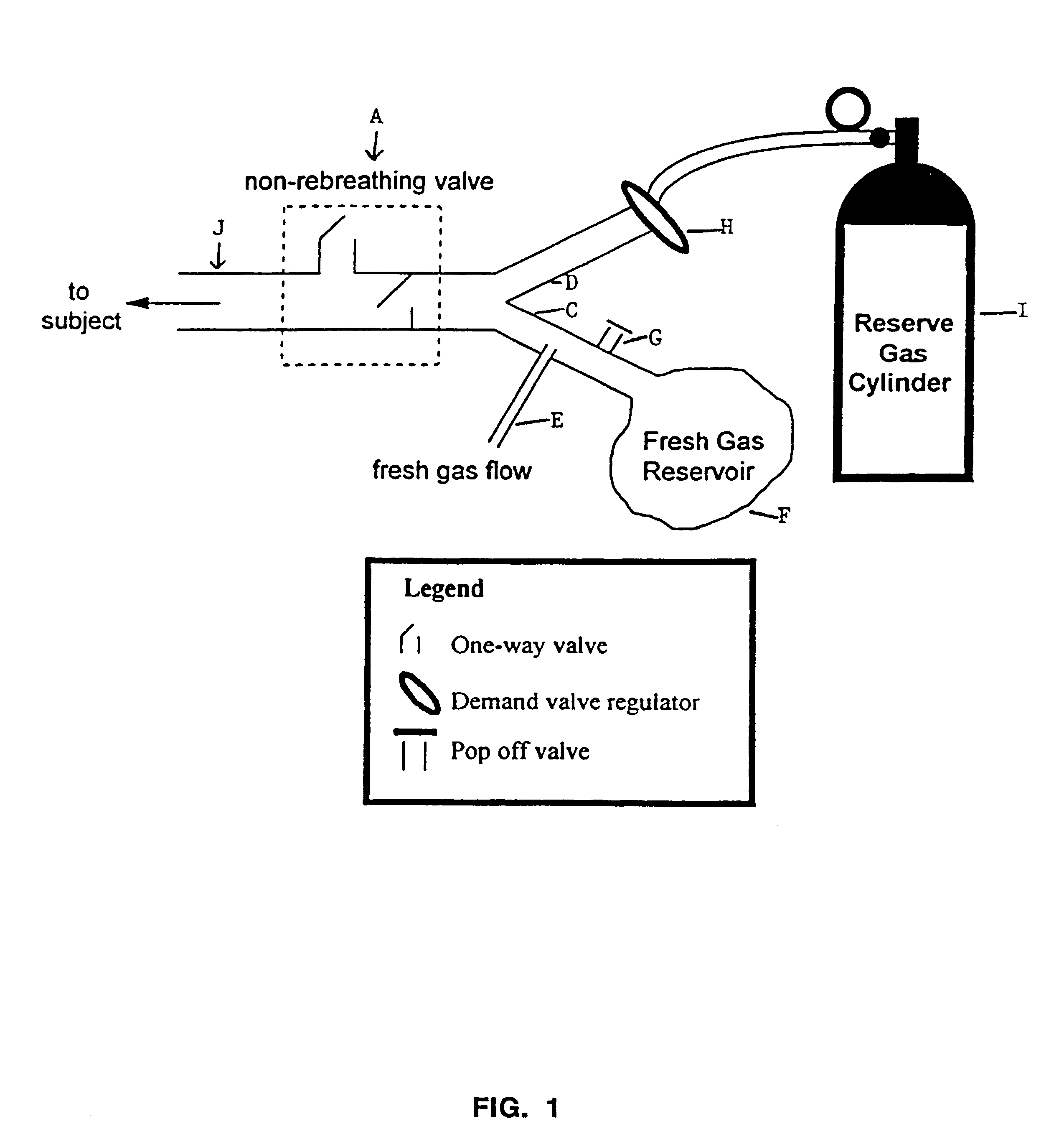
FIG. 1 illustrates schematically the nature of the simple breathing circuit and components which enable the patient to recover more quickly from vapour anaesthetics administration. The said device shown enables the PCO.sub.2 to remain constant despite increase in minute ventilation which thereby permits faster elimination of the vapour anaesthetic.

Problems solved by technology

However, the carbon dioxide is not eliminated from the lungs at a rate greater than the resting rate of the patient or a predetermined control rate.

Method used


Image

  • Elimination of vapour anaesthetics from patients after surgical procedures
  • Elimination of vapour anaesthetics from patients after surgical procedures
  • Elimination of vapour anaesthetics from patients after surgical procedures

Examples


Embodiment Construction

The circuit (FIG. 1) consists of a non-rebreathing valve (A) connected distally to two ports (C and D). The first port is connected in parallel to a source of fresh gas (E) (which does not contain CO.sub.2) and a fresh gas reservoir (F). A one-way pressure relief valve (G) prevents overfilling of the reservoir (F) by venting excess fresh gas. The second port (D) is connected via a one-way valve (H), to a source of gas (containing CO.sub.2) whose PCO.sub.2 is equal approximately to that of the mixed venous PCO.sub.2

We call this the "reserve gas" (I). Non-rebreathing valve A is connected to exit port J (from which the patient breathes).

Functional Analysis of Circuit Maintaining Constant PCO.sub.2 with Hyperventilation

When the minute ventilation "V" is less than or equal to the fresh gas flow "FGF" from (E), the subject inhales only fresh gas (non-CO.sub.2 -containing gas). When V exceeds FGF, the reservoir (F) containing fresh non-CO.sub.2 -containing gas empties first and the balance...


PUM


Abstract

A simple breathing circuit is designed to be added to a standard anesthetic circuit to hasten recovery of patients administered vapor anesthetic prior to an operation and also to method of treatments of a patient to hasten recovery from administration of vapor anesthetic prior to surgical procedures.

Description

The purpose of this invention is to provide a simple breathing circuit that can, for example, be added to a standard circle anaesthetic circuit known to persons skilled in the art to hasten recovery of patients administered vapour anaesthetics prior to an operation.This invention also relates to the use of the breathing circuit in hastening the recovery of patients who have been administered vapour anaesthetics prior to a surgical operation.This invention also relates to methods of treatment of patients to hasten their recovery from administration of the vapour anaesthetics to them prior to surgical procedures.PhysiologyVenous blood returns to the heart from the muscles and organs depleted of oxygen (O.sub.2) and full of carbon dioxide (CO.sub.2). Blood from various parts of the body is mixed in the heart (mixed venous blood) and pumped to the lungs. In the lungs the blood vessels break up into a net of small vessels surrounding tiny lung sacs (alveoli). The net of vessels surroundi...

Claims


Application Information

Patent Timeline
Patent Type & Authority Patents(United States)
IPC IPC(8): A61M16/00A61M16/10A61M16/12A61M16/20A61M15/00A61M16/01
CPCA61M16/00A61M16/12A61M16/208A61M2202/0225A61M2202/0007A61M16/22A61M16/209A61M16/024A61M16/0009
Inventor FISHER, JOSEPH A.
Owner FISHER JOSEPH A
Learn More