

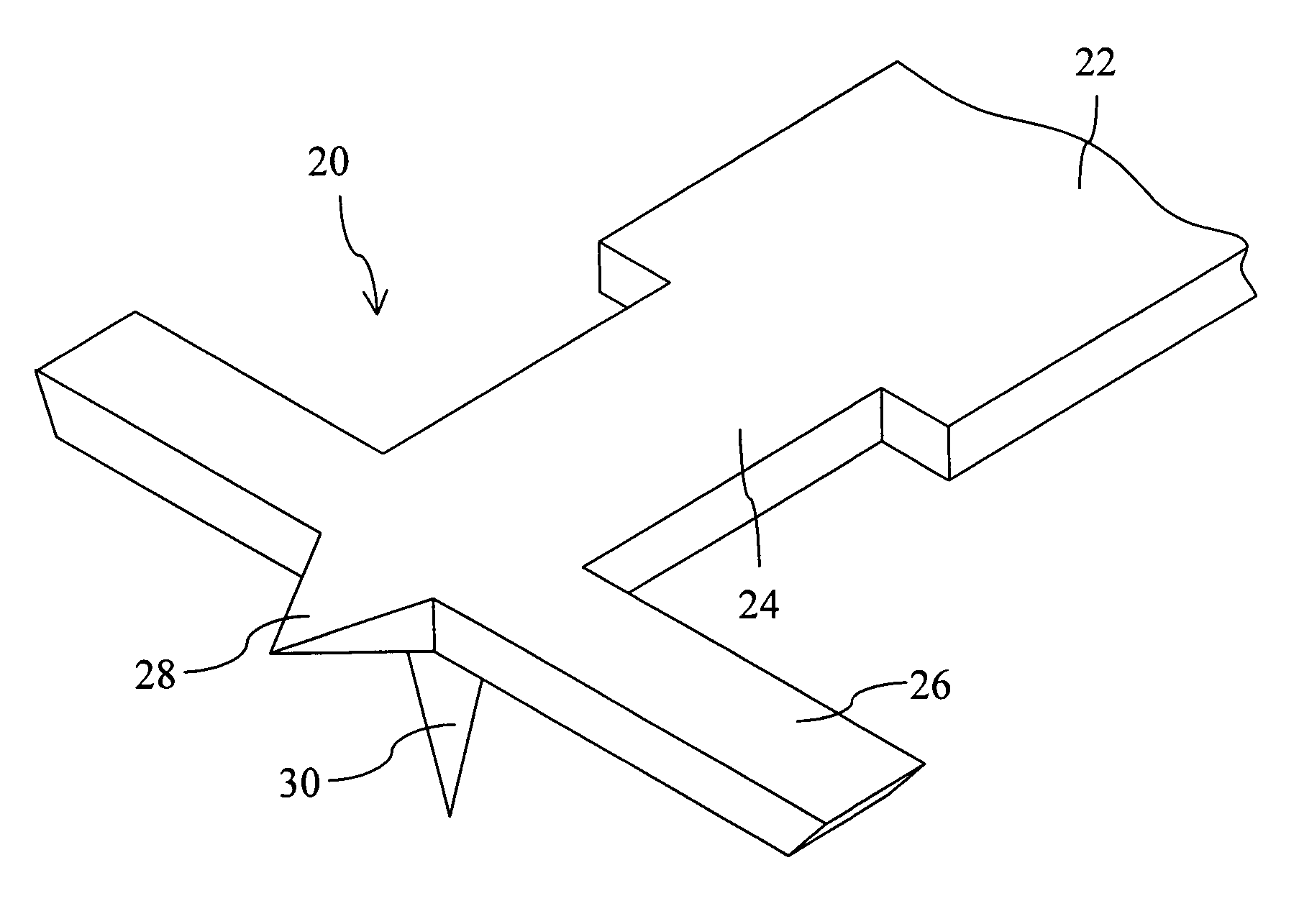
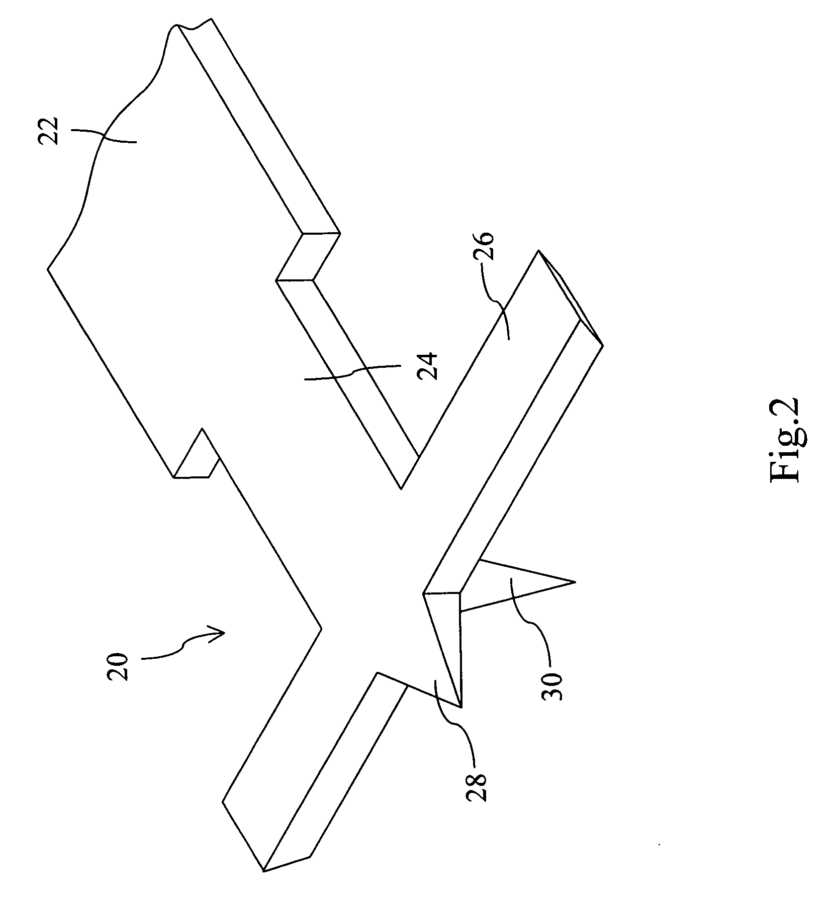
Front-wing cantilever for the conductive probe of electrical scanning probe microscopes
a scanning probe and microscope technology, applied in the direction of mechanical measurement arrangement, mechanical roughness/irregularity measurement, instruments, etc., can solve the problems of inferior contrast of differential capacitance image, inaccurate measurement of p-n junction width, and above problems that will become more serious for narrow energy gap materials, so as to promote analysis accuracy
- Summary
- Abstract
- Description
- Claims
- Application Information
AI Technical Summary
Benefits of technology
Problems solved by technology
Method used
Image

Examples
Embodiment Construction
[0024]Herein, the present invention is to be exemplified by Scanning Capacitance Microscopy (SCM); however, it is not intended to limit the scope of the present invention, and the application of the present invention to other Electrical Scanning Probe Microscopes, such as Scanning Spreading Resistance Microscopy (SSRM) and Conductive Atomic Force Microscopy (CAFM), are to be included within the scope of the present invention. The Scanning Capacitance Microscope primarily applies to the analysis of 2-dimensional distribution of carrier concentration and the measurement of the effective channel length of Metal Oxide Semiconductor (MOS) devices. However, the Scanning Capacitance Microscope is influenced by an optical perturbation, which brings about the increase in P-N junction measurement error and the decrease in image contrast. Owing to the above problems, when the Scanning Capacitance Microscope analyzes the carrier concentration distribution and the junction image within a nanomet...
PUM
| Property | Measurement | Unit |
|---|---|---|
| conductive | aaaaa | aaaaa |
| electrical scanning probe microscope | aaaaa | aaaaa |
| electrical | aaaaa | aaaaa |
Abstract
Description
Claims
Application Information