Method for cell alignment and identification and calibration of robot tool

a robot tool and cell technology, applied in the direction of programmed manipulators, testing/calibration of speed/acceleration/shock measurement devices, calibration apparatus, etc., can solve the problems of insufficient absolute accuracy to meet strict accuracy requirements, inability to detect erroneous calibration, and the update of robot programs with erroneous calibration data. achieve the effect of broadening the practical applicability and industrial usefulness, and increasing the degree of absolute accuracy

Inactive Publication Date: 2002-03-12
ROBOTKONSULT
View PDF11 Cites 19 Cited by
  • Summary
  • Abstract
  • Description
  • Claims
  • Application Information

AI Technical Summary

Benefits of technology

is to determine and calibrate the operating point of a tool and the location of the robot relative to the work pieces for the purpose of ensuring the ability of the installed application to exactly repeat programmed paths of travel over long periods without re-programming being needed.
Another technique is shown in SE 508 161, according to which a spherical calibration tool is mounted on a robot and is moved several times past a calibration beam. By repeating the process a large number of times, using different robot configurations, calibration of the robot is made possible.
The object of the invention is to satisfy the need for a method of cell alignment and identification and calibration of robot tools that is sturdy, permanently installed, and absolutely accurate, that may be repeated with precision, and is automatic, quick, and inexpensive, in order to ensure that the robot is capable of repeating with precision programmed paths of movement over long periods of time while being governed by the originally programmed points or paths. In some cases, calibration is not possible, and then the identification may be used to automatically transform all programmed points in a manner corresponding to the change of the detected parameters.
The method according to the invention offers considerable advantages. It is a high-technological and mathematically advanced method, which is applicable in the field, which directly operates on the objects of the application, and which optimizes the accuracy that is useful to the user.
The entire chain of precision of the application, including the position of the robot, the accuracy of the robot and the dimensions of the tool, is checked and / or is calibrated by analysis, resulting in information to the user of the accuracy available to him in the application executed by the robot. The method provides the user with a degree of accuracy that is optimized in one and the same operation and in terms of accuracy of use in the application in question. This method may give the application a higher degree of accuracy than the use of an individually calibrated robot comprising a separately and carefully measured tool and involving precisionmeasurement of the location of the robot relative to the workpiece, since this involves three separately suboptimized calibrations.
In addition, the method is applicable without knowledge of the kinematic model (equations) of the robot in question being necessary, a feature which broadens the practical applicability and the industrial usefulness, both because of the lesser requirements on separate adaptation to individual systems and because the kinematic models are difficult to access and in addition tend to become increasingly complex as the requirements from the market on absolute accuracy are becoming stricter (for which reason producing them is becoming increasingly time consuming unless one is in possession of special knowledge of the robot system in question).

Problems solved by technology

However, the degree of absolute accuracy has proved insufficient to meet strict demands for accuracy in connection with simulation of geometry and off-line programming of robots or manipulators.
Furthermore, it has been found that various types of defects, such as play that may arise in a tool or a robot axle, or friction in an axle, affect the method in a manner that may cause undetectable erroneous calibration.
Not only is this a time-consuming task but in addition it results in the robot program being updated with erroneous calibration data.
The consequence is loss of control of stop times in case of future incidents.
Also, one has found that minor but commonly occurring non-ideal situations may give rise to poor calibration repeatability.
This method is, however, time-consuming and expensive because of the special spherical calibration tool used, which must be applied to the robot at each and every instance of calibration.
Furthermore, calibration of the kind described in SE 508 161 is not particularly useful in connection with a robot located in a work environment but this prior-art method is more particularly concerned with pre-calibration of a robot before installation thereof in the workplace.
In addition, the method is applicable without knowledge of the kinematic model (equations) of the robot in question being necessary, a feature which broadens the practical applicability and the industrial usefulness, both because of the lesser requirements on separate adaptation to individual systems and because the kinematic models are difficult to access and in addition tend to become increasingly complex as the requirements from the market on absolute accuracy are becoming stricter (for which reason producing them is becoming increasingly time consuming unless one is in possession of special knowledge of the robot system in question).

Method used


Image

  • Method for cell alignment and identification and calibration of robot tool
  • Method for cell alignment and identification and calibration of robot tool

Examples


Embodiment Construction

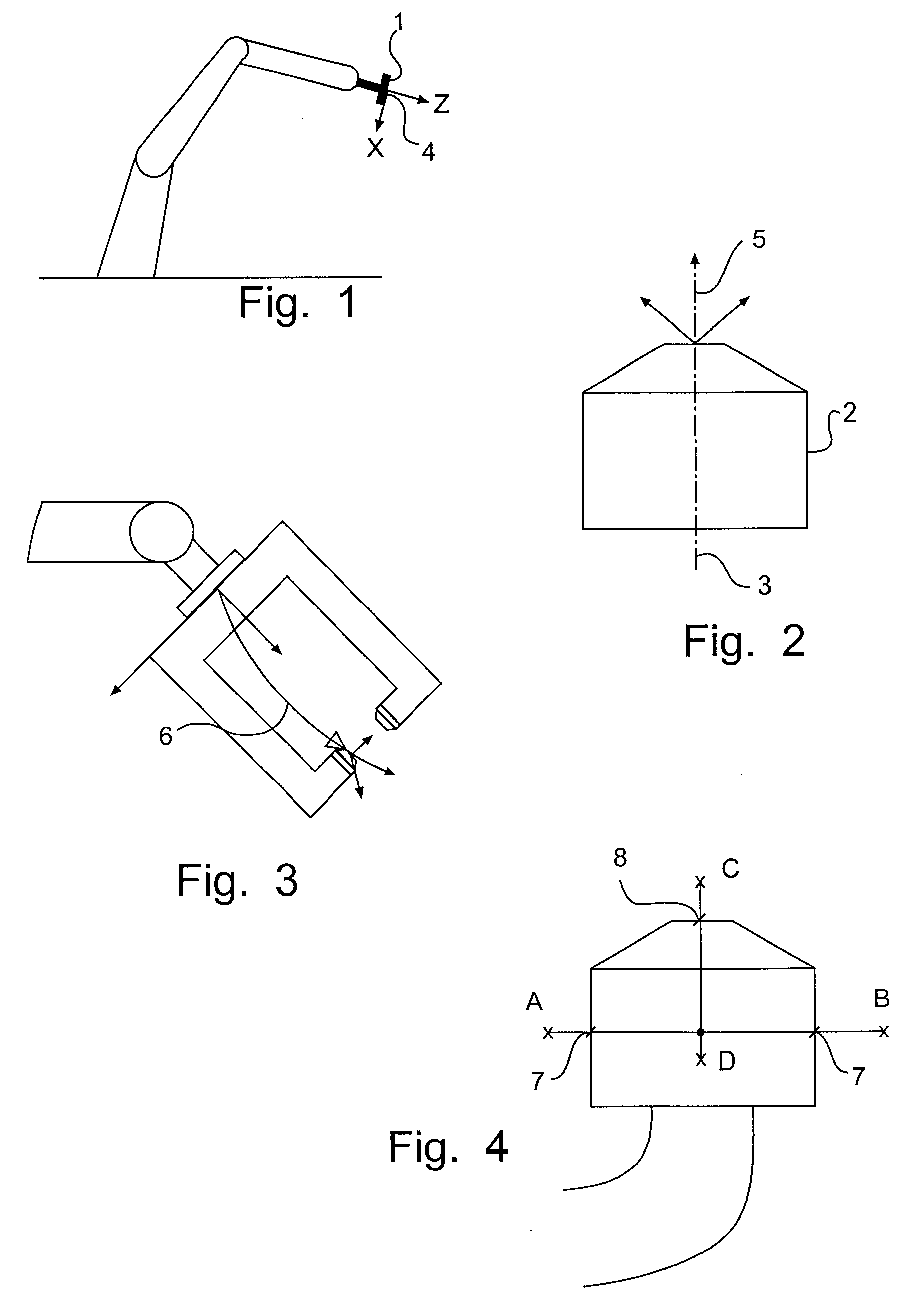
Initially, the invention will be described by means of one practical example in its special application in an industrial robot or manipulator applied for spot-welding by means of a robot-mounted gun having an essentially cylindrical welding electrode.

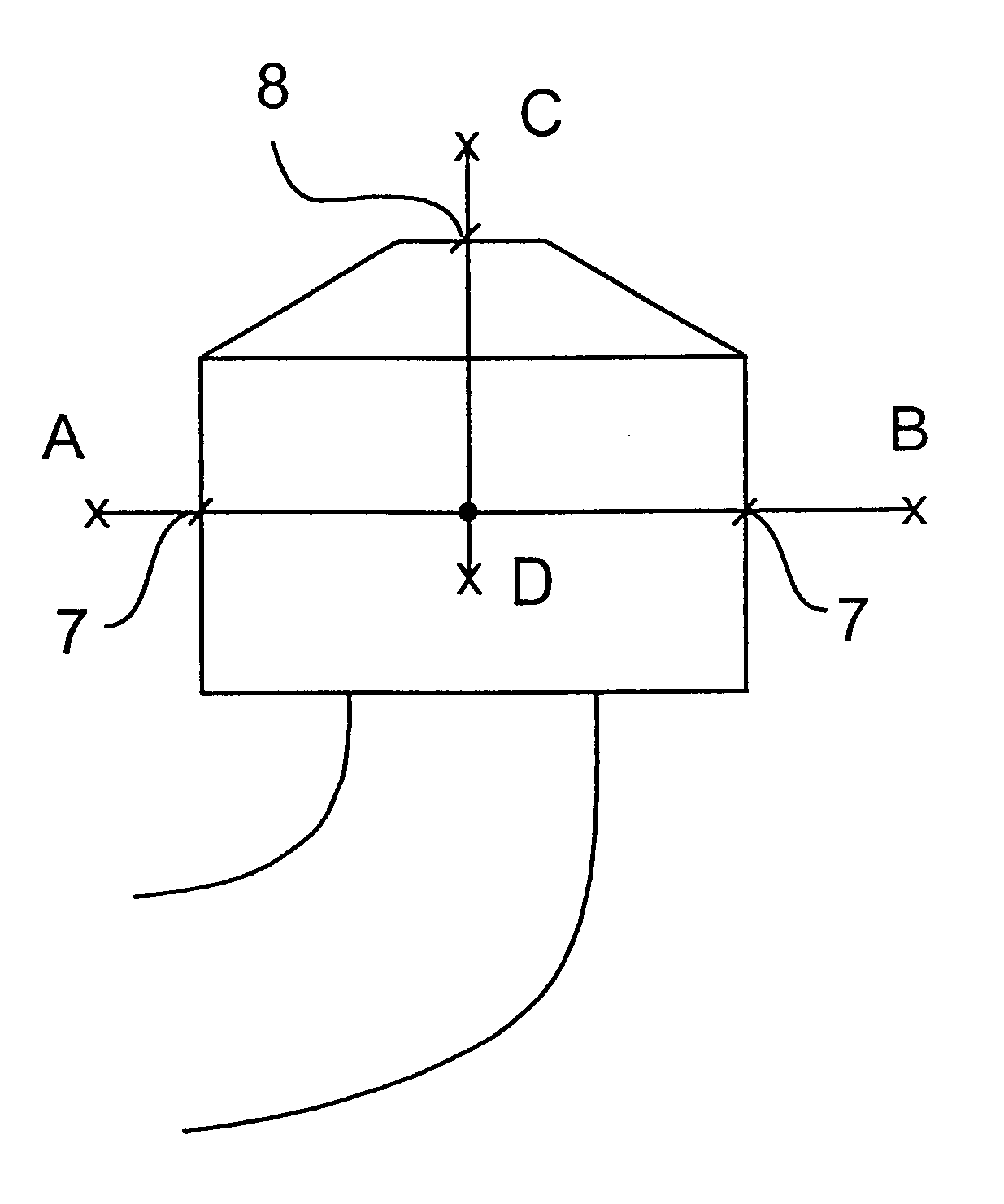
A spot-welding robot comprising a spot-welding gun normally comprises two welding electrodes, of which one is essentially stationary and the other mobile. In the present case, the stationary electrode 2 is of standard type and essentially cylindrical in shape, the cylinder axis being referenced by numeral 3. The purpose of calibrating the operating point of the tool is to determine the location of an operating position 5, which is unambiguously defined by the electrode geometry relative to the robot-hand coordinate system 4, which is unambiguously defined by the tool fastening plate 1 of the robot, when the gun is open and fixed equalizing achieved. Different users have different wishes in this respect, but the invention may be adapted ...


PUM


Abstract

A method for cell alignment, identification and calibration of part of a robot tool, preferably a part of the robot tool, is positioned close to a detector, whereupon it is moved repeatedly past the limit of the area of detection of the detector. During the movement, the pose of the robot is registered each time the surface of said robot tool comes into tangential contact with the area of detection, and an over determined system of equations is formed, consisting of a correlation between the registered poses and unknown parameters regarding the detection area of the detector and the location of the robot part in space. An error vector is introduced into the system of equations, which is then solved while minimizing the error vector, preferably in the least square sense, in order to thus identify said unknown parameters and the error vector.

Description

The invention concerns a method of cell alignment and identification and calibration of robot tools. More particularly, the object of the invention is to determine and calibrate the operating point of a tool and the location of the robot relative to the work pieces for the purpose of ensuring the ability of the installed application to exactly repeat programmed paths of travel over long periods without re-programming being needed.TECHNICAL BACKGROUNDThe state of the art is described in U.S Pat. No. 5 457 367. Methods of the kind defined in this patent specification have been used successfully for many years and have satisfied the most basic needs in a highly excellent manner.However, the degree of absolute accuracy has proved insufficient to meet strict demands for accuracy in connection with simulation of geometry and off-line programming of robots or manipulators. Furthermore, it has been found that various types of defects, such as play that may arise in a tool or a robot axle, o...

Claims


Application Information

Patent Timeline
Patent Type & Authority Patents(United States)
IPC IPC(8): B25J9/16B25J9/22B25J9/10G05B19/404
CPCB25J9/1692Y10S414/141
Inventor STENBERG, BJORN
Owner ROBOTKONSULT
Why Eureka
Try Eureka