
End play preload adjusting assembly for bearings

a technology of preload adjustment and bearing, which is applied in the direction of gearing details, mechanical equipment, and end play of etc., can solve the problems of not allowing for any variation or adjustment in the end play or preload applied to bearing sets, and it is difficult to achieve and maintain incremental adjustments of the small magnitude desired, and the magnitude of the adjustments permitted by the aforesaid arrangement is limited

Inactive Publication Date: 2002-03-19
DANA AUTOMOTIVE SYST GRP LLC
View PDF3 Cites 32 Cited by
  • Summary
  • Abstract
  • Description
  • Claims
  • Application Information

AI Technical Summary

Benefits of technology

It is still another object of the present invention to provide an adjusting assembly, as above, which assures that the selected end play and preloading will be maintained, and which can thereafter be further adjusted as necessary or desired, with relative ease.
It is yet another object of the present invention to provide an adjusting assembly which permits the desired preload for a bearing set to be exceeded in order to seat the bearing set correctly.

Problems solved by technology

However, other alternatives are often employed because of the difficulties heretofore experienced in adjusting the axial end play of, or the preload on, the races which support the rollers in a tapered bearing assembly.
Moreover, even if opposed, rigid shoulders could be provided, such an arrangement would not allow for any variation or adjustment in the end play of, or the preloading applied to, the bearing set.
It is, however, difficult to achieve and maintain incremental adjustments of the small magnitude desired by using a nut threaded onto the end of the shaft.
However, the magnitude of the adjustments permitted by the aforesaid arrangement is limited to a function of the thread pitch and the number of crenellations as well as their angular disposition.
However, the installation of a typical shim assembly generally requires a rather complicated series of steps.
The installation of prior known shim assemblies is, therefore, a relatively complicated process for which considerable expertise is required, and for which shims must be available in a wide variety of sizes in order for the desired end play or preloading to be effected.
The process and required spreader tool substantially increases the assembly time and cost.
The need to provide threaded bores, however, creates a problem in that while the aforementioned cams or ramps will allow for an infinite array of settings, discrete placement of threaded bores to receive the bolts severely restricts usage of the array to that permitted by the particular placement of the bores.

Method used


Image

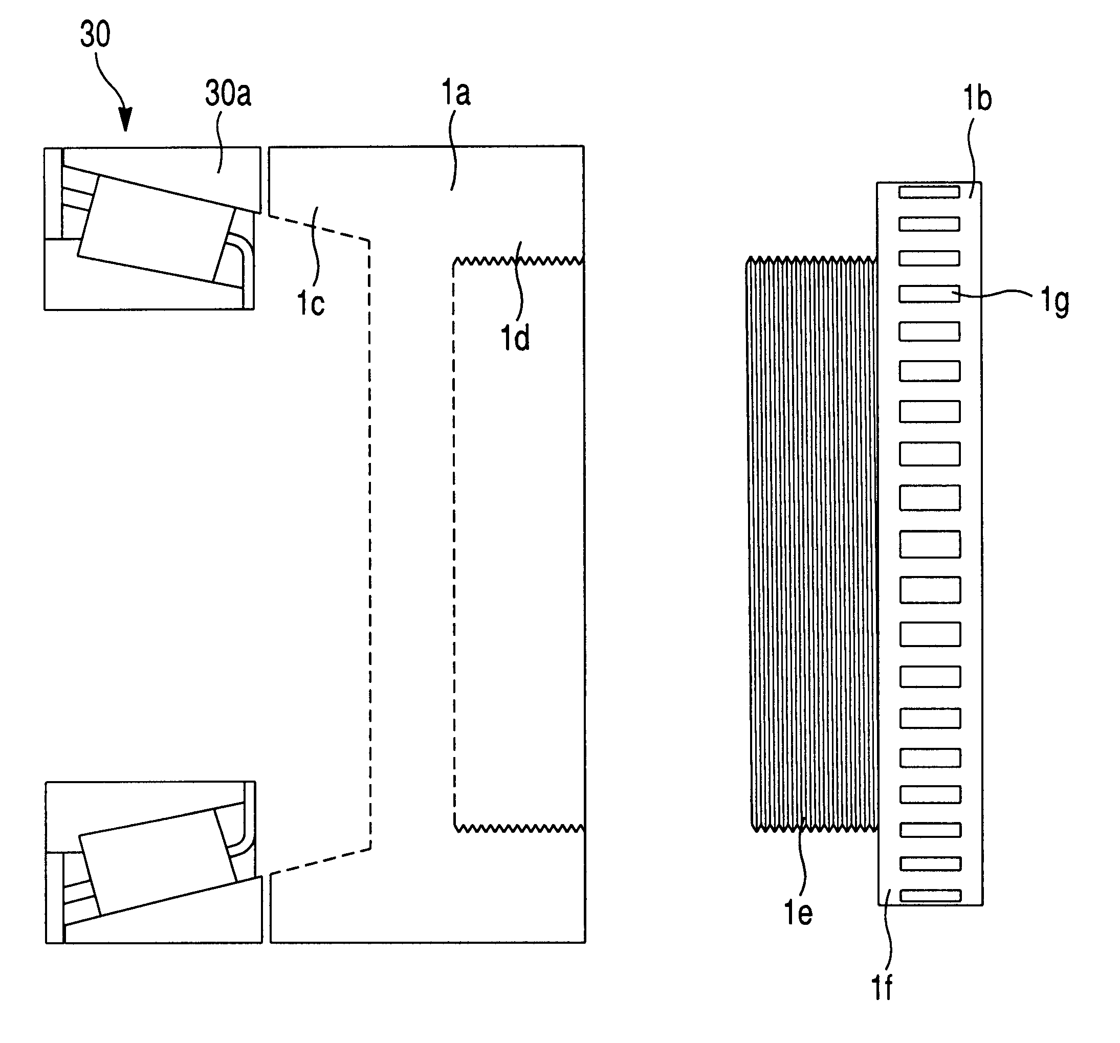
  • End play preload adjusting assembly for bearings
  • End play preload adjusting assembly for bearings
  • End play preload adjusting assembly for bearings

Examples


Embodiment Construction

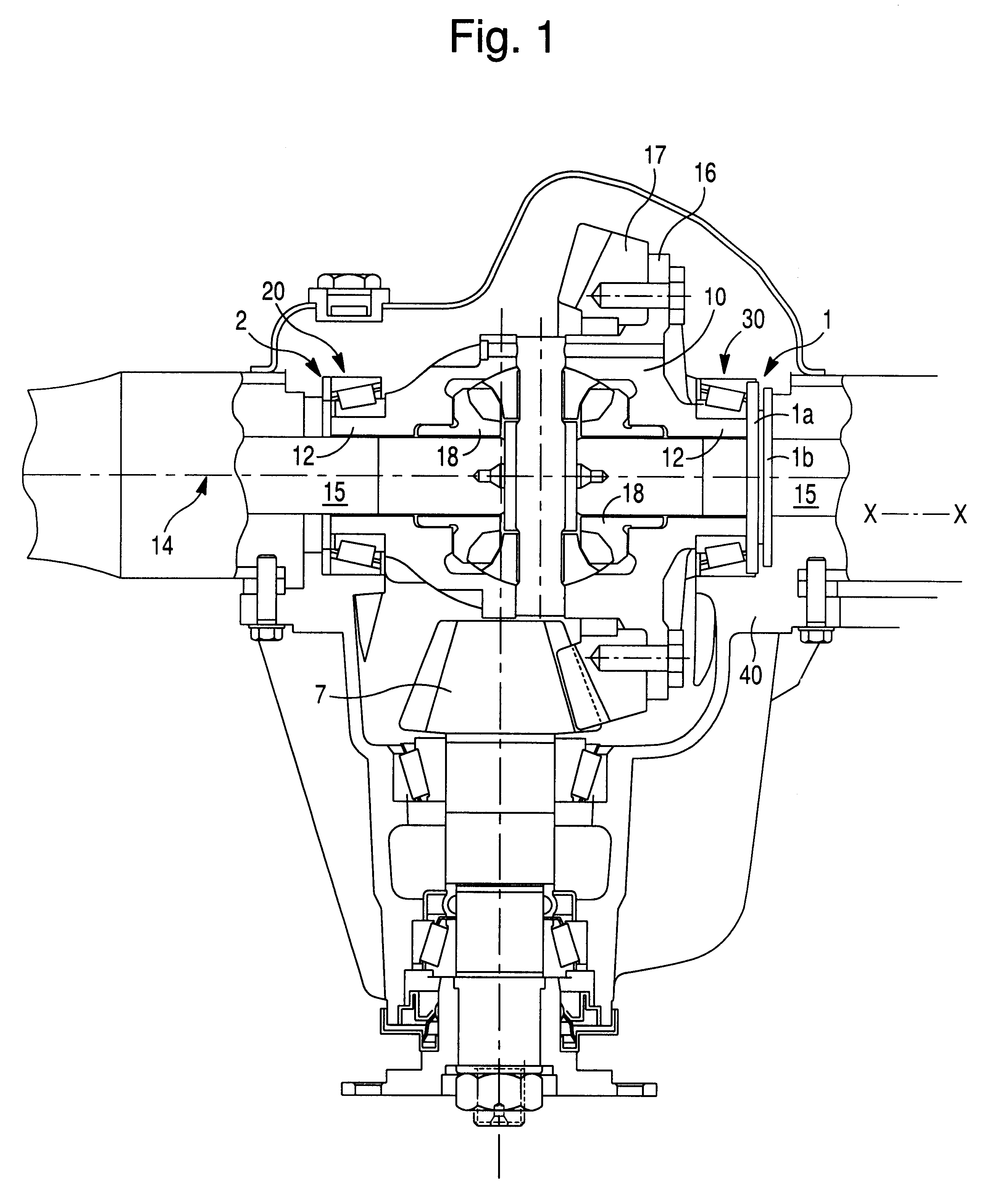
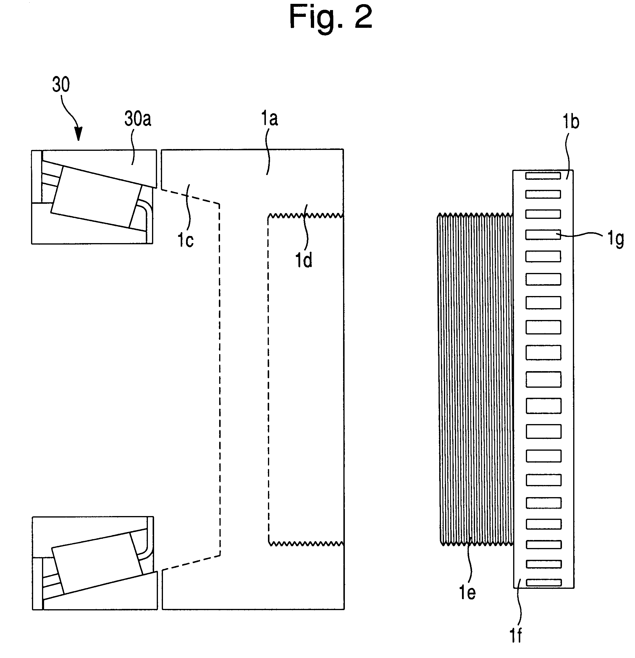
One representative form of an adjusting assembly embodying the concepts of the present invention is designated generally by the numeral 1 on the accompanying drawings showing a differential assembly. It is understood that the present invention is not limited to this environment but instead provides an adjustment assembly suitable for a variety of systems employing a tapered bearing assembly.

FIG. 1 of the drawings illustrates a differential assembly in accordance with the present invention comprising a differential case 10 having opposing axial spigots 12 at each end thereof. The spigots 12 are provided to mount the case 10 for rotation about an axis 14 on rolling bearings 20, 30 supported by a differential carrier 40. The differential case 10 has an external flange 16 with circumferentially spaced holes for attachment by bolts to a ring gear 17. The ring gear 17 meshes with an input pinion 7 connected to a driveline of a motor vehicle (not shown).

The differential case 10 forms a hol...


PUM


Abstract

An assembly to effect adjustments to the end play, or preloading, of a bearing set. The adjusting assembly utilizes a threaded bearing cup body and a correspondingly threaded adjusting ring. The bearing cup body abuts the outer race of the bearing and the adjusting ring is threaded onto the bearing cup body and abuts a fixed or stationary housing surface. The adjusting ring is rotated to adjust bearing preload and provide proper spacing. The bearing cap is then placed to lock the bearing adjusting assembly in place.

Description

1. Field of the InventionThe present invention relates to bearing mounts. More particularly, the present invention relates to a simplified adjustment assembly which interacts between a bearing assembly and the housing within which the bearing assembly is supported. Specifically, the present invention relates to an assembly by which to effect incremental adjustments to the axial end play of, or the preload on, the outer race of a bearing assembly, either alone or in a set.2. Description of Related ArtEven with journal arrangements for which thrust loading is not reasonably anticipated, and within which cylindrical bearings are appropriate to support radial loading, it is customary to utilize some structure by which to effect axial retention of the bearings that rotatably support a shaft, or the like. This is done so that should the shaft, even unexpectedly, apply a reasonable thrust load on the bearing, the bearing will remain seated within the housing. When the environment in which ...

Claims


Application Information

Patent Timeline
Patent Type & Authority Patents(United States)
IPC IPC(8): F16C25/00F16C25/06F16C19/36F16C19/54F16C19/22F16C19/00F16H48/06F16H57/02F16H48/00F16C25/08F16H57/022
CPCF16C19/364F16C19/54F16C25/06F16H2057/0221F16H48/06F16C2229/00F16C2361/61
Inventor MYERS, LESLIE DEANDOYLE, GARY PETER
Owner DANA AUTOMOTIVE SYST GRP LLC
Learn More