Method and device for measuring forces

a force measurement and force technology, applied in the field of methods and force measurement apparatuses, can solve the problems of friction force f.sub.fr generating unbalanced momentum and torsion deformation, unbalanced momentum and deformation in the force measurement system, and the upper specimen has a leverage with respect, etc., to achieve the effect of limiting freedom of movement and removing misbalan

Inactive Publication Date: 2002-04-02
NEVMET CORP
View PDF3 Cites 35 Cited by
  • Summary
  • Abstract
  • Description
  • Claims
  • Application Information

AI Technical Summary

Benefits of technology

The device of the invention for force measurement in a friction tester comprises an assembly of two deformation-sensitive sensors for simultaneous equal deformation in two opposite directions for eliminating misbalance created in the measurement system when a tester with a single sensor is used. Each sensor comprises a deformable beam having through longitudinal slots extending in different and non-parallel directions and overlapped within the body of the beam. Each sensor deforms in one direction under the effect of a loading force measured by two strain gauges located on opposite sides of the beam near

Problems solved by technology

A disadvantage of this device is that the upper specimen has a leverage with respect to the point of attachment of the lower specimen, i.e., with respect to its center.
As a result, the loading force applied to the lower specimen via the upper probe, as well as the reaction force applied to the probe from the lower specimen create an unbalanced momentum and deformations in the force measurement system.
Similar problem occurs in a mechanism for attachment of a bi-directional force sensor in a friction tester, as disclosed

Method used


Image

  • Method and device for measuring forces
  • Method and device for measuring forces
  • Method and device for measuring forces

Examples


Embodiment Construction

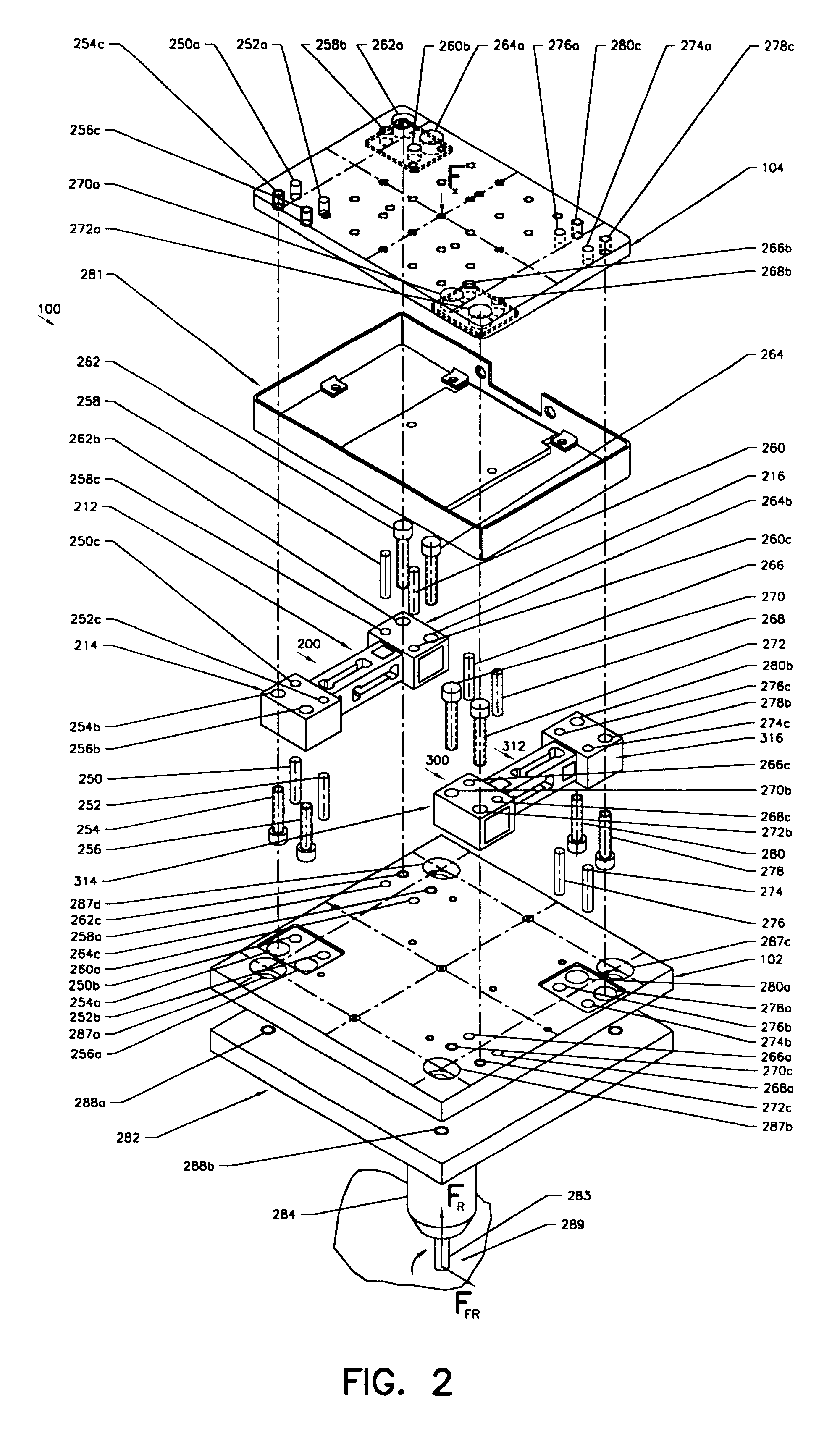
FIG. 2 is a three-dimensional exploded view of a device of the invention for force measurement in a friction tester. As can be seen from this drawing, the device, which in general is designated by reference numeral 100, consists of a lower plate 102 of a rectangular shape, an upper plate 104 which has substantially the same shape and dimensions as the plate 102, and a pair of sensors 200 and 300 sandwiched between the lower plate 102 and the upper plate 104. The upper plate 104 is connected to a loading unit of a friction testing apparatus (not shown), and the lower plate 102 supports a stationary upper specimen, which during testing is maintained in contact with a moveable lower specimen. The specimens will be shown and described later in connection with operation of the device. Both sensors are spaced from each other and are arranged symmetrically diagonally opposite to each other. In other words, the sensor 200 is located in a position turned 180.degree. with respect to the senso...


PUM


Abstract

The device of the invention is intended for measuring a loading force and a friction force in a tribological tester. The device consists of two deformation-sensitive sensors for simultaneous equal deformation in two opposite directions for eliminating misbalance created in the measurement system when a single sensor is used. Each sensor is a deformable beam having through longitudinal slots extending in different and non-parallel directions and overlapped within the body of the beam. The sensor deforms in one direction under the effect of a loading force measured by two pairs of strain gauges located on opposite sides of the beam near one end of the beam and in another direction under the effect of a friction force measured by another two pairs of strain gauges located on opposite sides of the beam near the other end of the beam. Two sensors are sandwiched between two plates in a diagonally symmetrical positions so as to transmit forces between both plates and at the same time to ensure limited freedom of movement between both plates to allow deformations caused by the applied forces. One plate may be attached to the loading unit of the tester and another plate may support an upper sample for engagement with the lower sample of the tester.

Description

The present invention relates to force measurement technique, in particular to a method and apparatus for measuring friction forces on a friction tester.Tribology is a science of friction, wear, and lubrication on friction surfaces. Many different types of friction testers, tribometers, and other devices for measuring various parameters of friction are known. One such friction tester is disclosed in U.S. Pat. No. 5,795,990 issued to Norm Gitis, et al in 1998. This tester has a lower disk-like test material specimen and an upper rod-like test material specimen or probe which performs orbital motions while being in contact with a stationary lower specimen. A disadvantage of this device is that the upper specimen has a leverage with respect to the point of attachment of the lower specimen, i.e., with respect to its center. As a result, the loading force applied to the lower specimen via the upper probe, as well as the reaction force applied to the probe from the lower specimen create a...

Claims


Application Information

Patent Timeline
IPC IPC(8): G01L1/22G01L5/16G01L5/00G01L1/20G01N19/02
CPCG01L1/2243G01L5/162G01L5/0076G01N19/02
Inventor GITIS, NORMVINOGRADOV, MICHAELDORFMAN, VLAD
Owner NEVMET CORP
Why Eureka
Try Eureka