Adjusting an electronic camera to acquire a watermarked image

a technology of electronic cameras and watermarks, which is applied in image enhancement, television systems, instruments, etc., can solve the problems of not always producing optimal conditions for detecting digital watermarks, and the optimal settings of cameras used in such systems are not necessarily optimal settings, so as to improve the characteristics, exposure time and gain of electronic cameras

Inactive Publication Date: 2002-04-02
ENGELHARD CORP
View PDF4 Cites 62 Cited by
  • Summary
  • Abstract
  • Description
  • Claims
  • Application Information

AI Technical Summary

Problems solved by technology

It has been found that the optimal settings for a camera used in such systems is not necessarily the optimal settings that are established to provide a pleasing image to a human viewer.
The type of parameters that can be established using a menu such as that shown in FIG. 1 do not always produce optimal conditions for detecting a digital watermark in an acquired image.

Method used


Image

  • Adjusting an electronic camera to acquire a watermarked image
  • Adjusting an electronic camera to acquire a watermarked image
  • Adjusting an electronic camera to acquire a watermarked image

Examples


Embodiment Construction

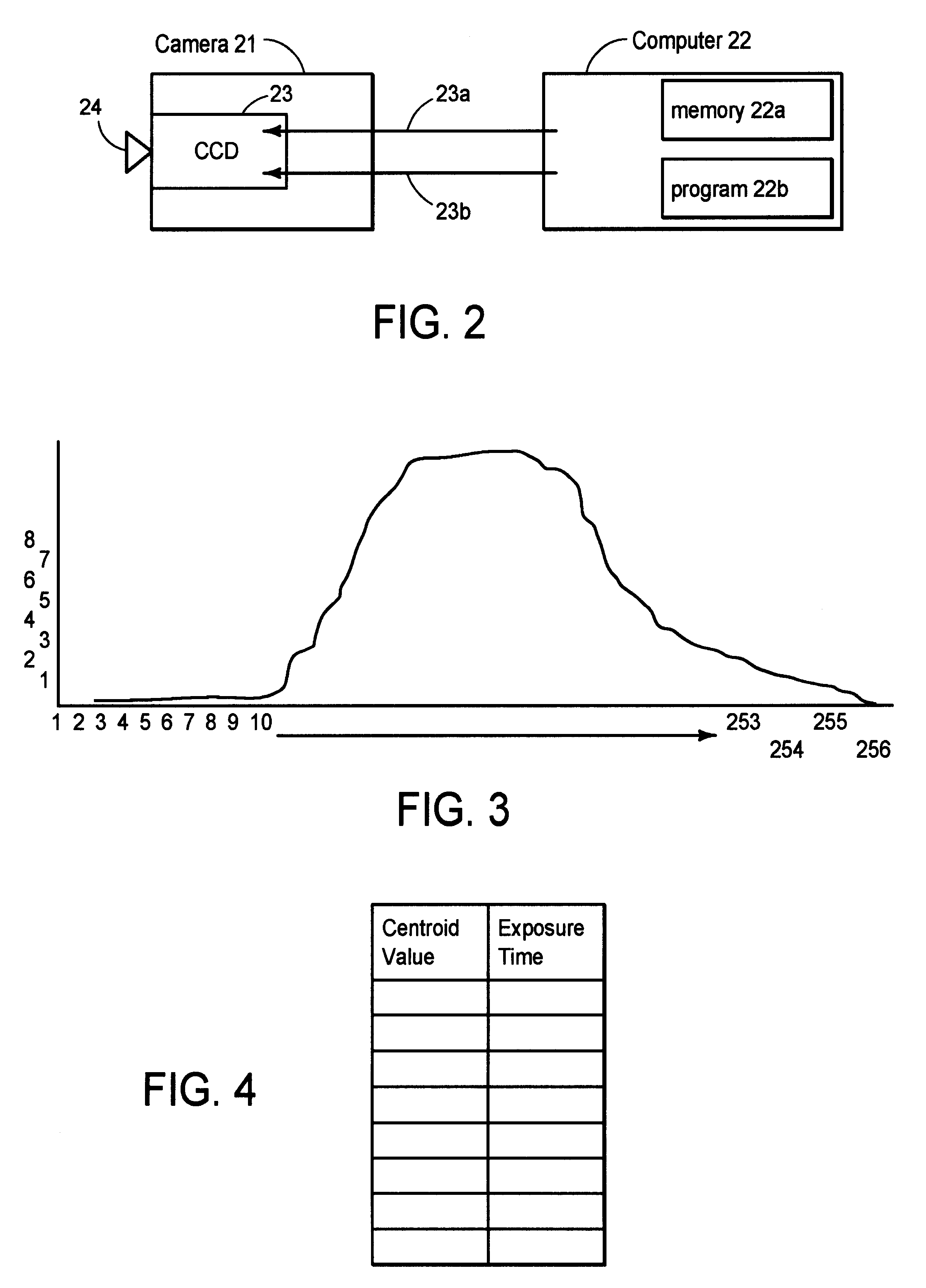
The overall system shown in FIG. 2 includes a conventional digital camera 21 and a conventional control computer 22. As is conventional the camera 21 includes a CCD detector 23 and a lens 24 which focuses an image on the CCD detector. The CCD detector 23 has a gain control line 23a and an exposure control line 23b. The control computer 22 controls the values on the lines 23a and 23b. While for convenience of illustration and explanation the camera 21 is shown in FIG. 2 as an individual unit separated from control computer 22, it should be understood that in many commercially available systems the camera 21 is mounted within (or attached to) the computer 22 and lines 23a and 23b represent logical control lines rather than physical wires.

As is conventional the computer 22 includes memory 22a and programming 22b. For convenience and clarity of illustration and explanation these are illustrated as separate boxes in FIG. 2. The other conventional parts of the camera 21 and the computer 2...


PUM


Abstract

The present invention provides a mechanism for automatically setting the exposure time and gain of an electronic camera so that the acquired image has improved characteristics for the detection of a digital watermark. With the present invention the exposure time and gain of an electronic camera are set by first directing the camera at a test target with the camera's controls set to a default set of values. The system then calculates a histogram of the luminance values of the pixels in the image. Next characteristic values from the histogram such as the peak value, the centroid value, the RMS value, the median value, etc. are calculated. One or more of the characteristic values of the histogram are then applied as an index or pointer to values of pre-established settings that are stored in a table. Values from the table are used to set the exposure time and / or gain of the camera. In some embodiments, the variance of the luminance histogram is also measured and used to index data from the table.

Description

This invention relates to electronic cameras and more particularly to the control of electronic cameras.Electronic cameras are commercially available and in widespread use. The basic technology used in electronic cameras is well developed. Electronic cameras generally include CCD or CMOS light sensing elements. The exposure time of the light sensing elements and the gain of the readout circuitry can be set to control the quality of the images which are acquired by the camera.Some electronic cameras have a built in exposure meter that detects the amount of light reaching the camera. The appropriate exposure time and gain of the sensing elements is then automatically set at values determined by the signal generated by the exposure meter.Some electronic video cameras which are designed for integration into a personal computers provide the user with a menu such as that shown in FIG. 1 which can be used to set various parameters to control the operation of the camera. A user typically se...

Claims


Application Information

Patent Timeline
Patent Type & Authority Patents(United States)
IPC IPC(8): G06T5/40G06T1/00
CPCG06T1/0021G06T5/007G06T5/40G06T2201/0065G06T2201/0051G06T2201/0052G06T2200/24
Inventor BRUNK, HUGHROGERS, ELIOTHANNIGAN, BRETT T.
Owner ENGELHARD CORP
Why Eureka
Try Eureka