Multi-bit error correction system

a multi-bit error correction and error detection technology, applied in the field of error detection and correction systems, can solve problems such as too slow reed-solomon codes

Inactive Publication Date: 2002-04-02
IBM CORP
View PDF13 Cites 36 Cited by
  • Summary
  • Abstract
  • Description
  • Claims
  • Application Information

AI Technical Summary

Problems solved by technology

Unfortunately, for the demands of many current appli...

Method used


Image

  • Multi-bit error correction system
  • Multi-bit error correction system
  • Multi-bit error correction system

Examples


Embodiment Construction

Illustrative embodiments and exemplary applications will now be described with reference to the accompanying drawings to disclose the advantageous teachings of the present invention.

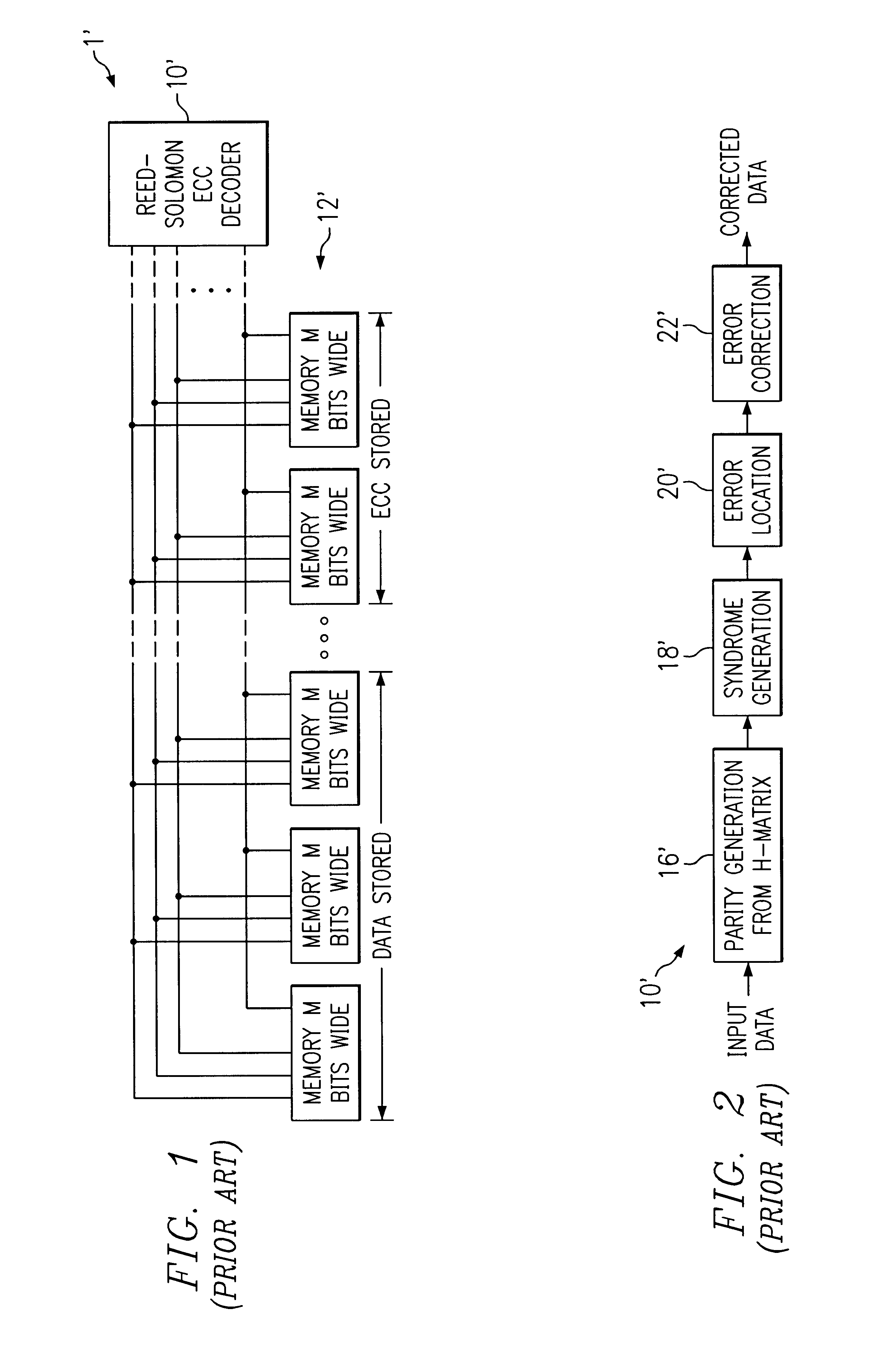
FIG. 1 is a block diagram of a conventional error correcting system 1' with an error correcting code decoder 10' and memory 12'. The decoder 10' is shown as a Reed-Solomon decoder. Note that the Reed-Solomon decoder handles all of the data in a digital word at one time. This is illustrated with reference to FIGS. 2 and 3 below.

FIG. 2 is a simplified block diagram of a typical error correcting code decoder 10'. The decoder 10' includes a parity generation circuit 16', a syndrome generator 18', an error locator 20' and an error corrector 22'.

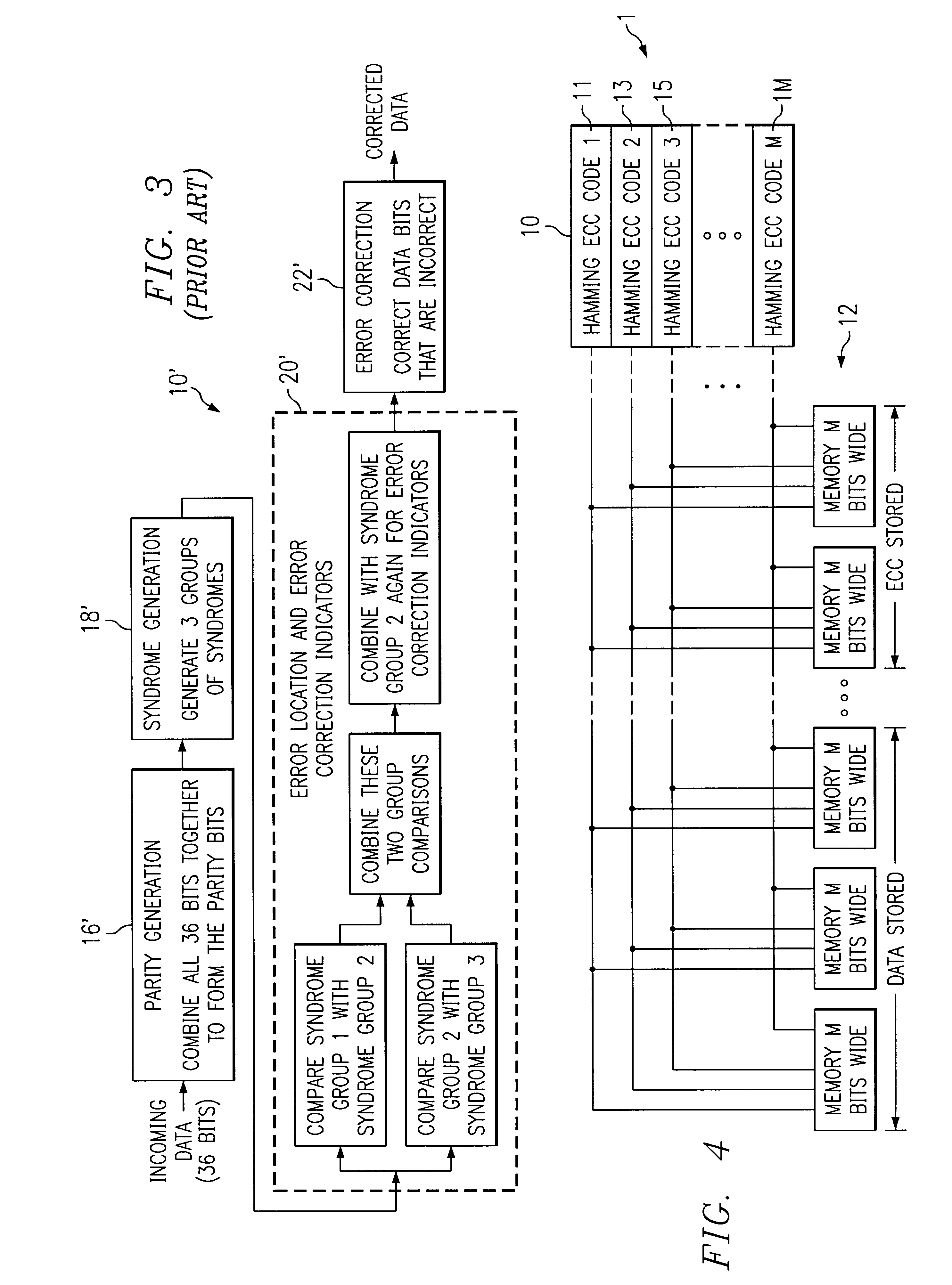
If the decoder 10' is a Reed-Solomon decoder, it may operate as shown in FIG. 3. For a 36 bit data word, the parity generator 16' is an array of exclusive OR gates which combines all 36 bits together to form parity bits. The syndrome generator 18' is also typically imp...


PUM


Abstract

An improved multi-bit error correction system. The inventive error correcting system performs a fast error correction operation on individual bits within multi-bit modules. In a specific implementation, the invention uses Hamming codes and divides an n times m bit data word into m modules, with each module having n bits. Next, the ith bits of each module are combined to form a set of parity bits. Syndrome bits are generated from the parity bits and used to locate errors in the bits and provide an indication of same. Finally, errors in the bits are corrected in a conventional manner to provide corrected data bits.

Description

1. Field of the InventionThe present invention relates to digital data communication, processing, storage and retrieval. More specifically, the present invention relates to error detection and correction Systems for digital data communication, processing storage and retrieval systems.While the present invention is described herein with reference to illustrative embodiments for particular applications, it should be understood that the invention is not limited thereto. Those having ordinary skill in the art and access to the teachings provided herein will recognize additional modifications, applications, and embodiments within the scope thereof and additional fields in which the present invention would be of significant utility.2. Description of the Related ArtFor certain applications, accurate communication, processing, storage and retrieval of digital data is critically important. For these applications, error detection and correction schemes are employed to detect and, in many case...

Claims


Application Information

Patent Timeline
IPC IPC(8): H03M13/00H03M13/11H03M13/19G06F11/10
CPCG06F11/1008H03M13/6561H03M13/27H03M13/19
Inventor CHAPMAN, RONALD JAMESCHRISTENSEN, ARIEL BRENTJONES, CARL EVANPARANJAPE, SUSHAMA MAHESH
Owner IBM CORP
Why Eureka
Try Eureka