Error correcting method and apparatus

a technology of error correction and error correction, applied in the field of error correction methods and apparatuses therefor, can solve problems such as enlarge circuit scale, transfer delay, and rs code cannot accurately count the number of error bits

Inactive Publication Date: 2004-04-27
FUJITSU LTD
View PDF15 Cites 14 Cited by
  • Summary
  • Abstract
  • Description
  • Claims
  • Application Information

AI Technical Summary

Benefits of technology

Namely, the Hamming code is required to temporarily hold all of the information on a receiver side when an error correction is performed. The transfer delay is caused for the holding time. By dividing a single frame into L Hamming code blocks and making the size of a single Hamming code block 1 / L of a single frame, the transfer delay is reduced.
As a result, the BER is improved in the B2 operation, so that the number of a line switchover frequency by the SD alarm can be reduced.

Problems solved by technology

However, the RS code requires a memory on the transmitter side and enlarges a circuit scale.
Furthermore, assuming that the number of bits in one character is "n", the RS code notifies that the number of errors is "1" in case the number of error bits is any one of 1 to n. Accordingly, the RS code can not accurately count the number of error bits.
The transfer delay is caused for the holding time.
Accordingly, a burst or sequential bit error can not be corrected.
The transfer delay is caused for the holding time.
Accordingly, a start time for processing the next Hamming code block is delayed with single syndrome registers, which makes it difficult to follow the transmission speed of frame.
For example, when the FEC function is performed after the B2 byte operation, a B2 byte error occurs when the B2 byte operation is performed without performing the FEC function on the receiver side because FEC error correcting bytes are included in the operation range of the B2 byte portion.

Method used


Image

  • Error correcting method and apparatus
  • Error correcting method and apparatus
  • Error correcting method and apparatus

Examples


Embodiment Construction

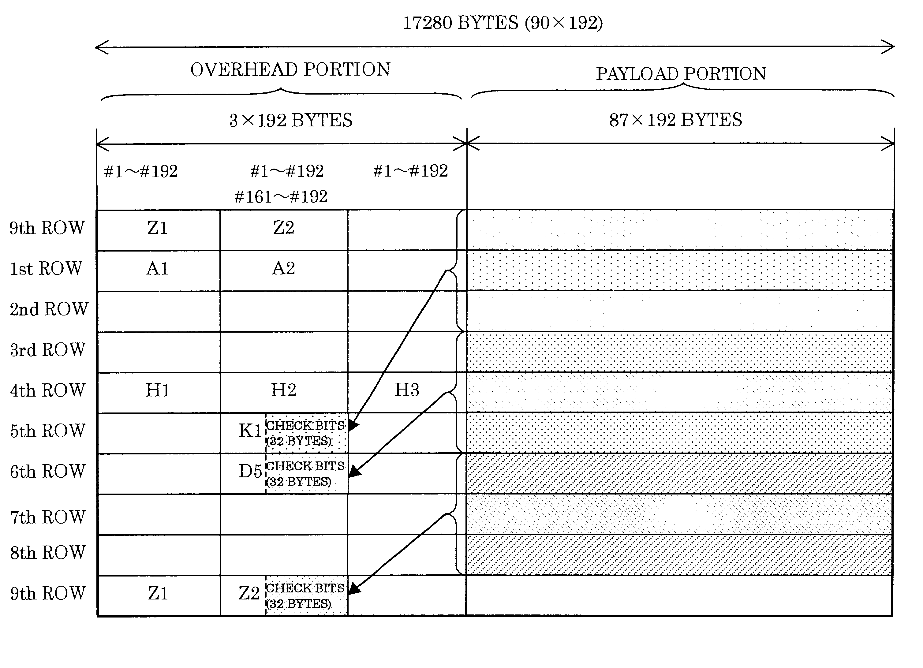
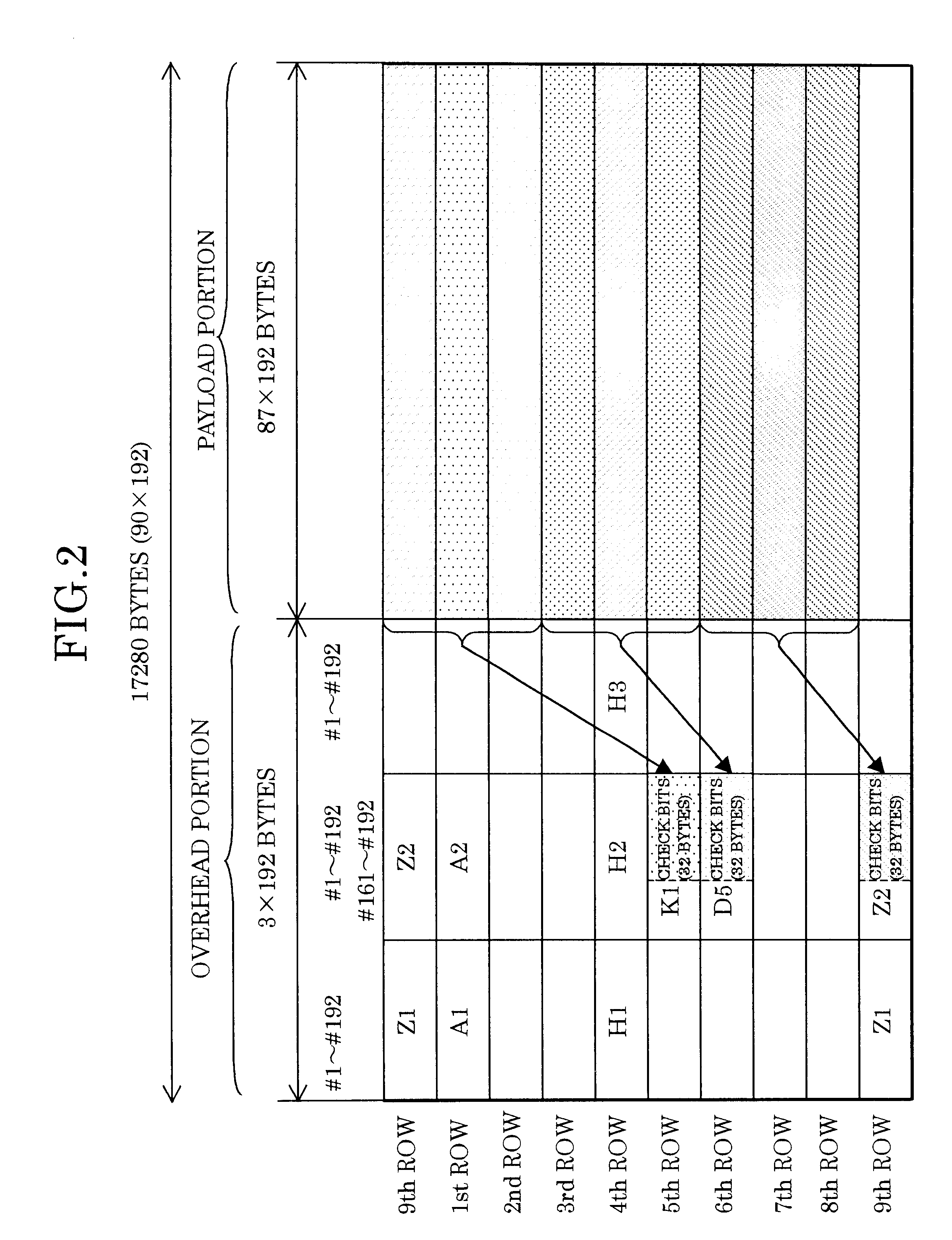
FIG. 2 shows an embodiment of an STS-192 frame used in an error correcting method and apparatus according to the present invention. The payload portion is divided into L, i.e. three information bit blocks with each 50112 bytes (=87 bytes.times.192.times.3) of 9th, 1st, 2nd rows, 3rd-5th rows, and 6th-8th rows forming one block, so that K1, D5, and Z2 byte portions consisting of 32 bytes in the LOH portion are respectively allotted to each of the blocks as check bit blocks.

FIGS. 3-5 respectively show each of three information bit blocks and three check bit blocks shown in FIG. 2.

FIG. 3 shows the block of 9th, 1st, 2nd rows in the payload portion and the block of the K1 byte portion in the LOH portion corresponding to that block. In the 9th, 1st, 2nd rows, the block of the payload portion is further divided into mini blocks 701-716, mini blocks 717-732, and mini blocks 733-748 each of which has 1044 bytes (=87 bytes.times.192 / 16).

The combination of mini blocks in each row, such as the...


PUM


Abstract

In an error correcting method and an apparatus therefor using Hamming codes, a frame regulated by a synchronous network is divided into L blocks in the direction of row. Preferably, information bits and check bits are allocated to a payload portion and non-defined bits of an LOH portion, respectively. More preferably, the information bits and the check bits are divided into M sub blocks to form a Hamming code block. In addition, a code error correcting means rearrange each Hamming code block per bit and further preferable, a syndrome register with a plurality of banks operates an error syndrome of the Hamming code block, and based on the operation result, the code error correction of the Hamming code block is performed by a bank switchover.

Description

1. Field of the InventionThe present invention relates to an error correcting method and an apparatus therefor, and in particular to a method and an apparatus for performing an error correction of a transmission signal with a Hamming code.In a long distance transmission line of an optical transmission equipment by way of example, a loss caused by an optical fiber is compensated by the cascade connection of optical amplifiers, while a noise generated at each of the optical amplifiers deteriorates network quality parameters, e.g. a BER (Bit Error Rate).As an efficient method to solve this problem, an error correcting method and an apparatus therefor are required by a transmitter making a message an error correcting code to be transmitted and a receiver detecting an error bit included in a received message to correct the bit.2. Description of the Related Art(1) It is known as a prior art error correcting method that for example, in "Design and Characterization of an Error-Correction Co...

Claims


Application Information

Patent Timeline
Patent Type & Authority Patents(United States)
IPC IPC(8): H03M13/19H03M13/00G06F11/10
CPCH03M13/19H04L1/0075H04L1/007H04L1/0053H04L1/0041
Inventor ISHIWATARI, JUNICHITANIGUCHI, ATSUKISHIODA, MASAHIROKUWABARA, TAKASHIYAMAZAKI, YUKIO
Owner FUJITSU LTD
Why Eureka
Try Eureka