Non-contacting sensor for measuring relative displacement between two rotating shafts

Inactive Publication Date: 2002-04-09
CTS CORP ELKHART
View PDF17 Cites 108 Cited by
  • Summary
  • Abstract
  • Description
  • Claims
  • Application Information

AI Technical Summary

Problems solved by technology

There are several problems occurring with the prior art.
A large amount of torque on the steering wheel occurs at low speed operation or during parking.
In a hydraulic power steering system, the power steering pump is always being turned by the engine and represents

Method used


Image

  • Non-contacting sensor for measuring relative displacement between two rotating shafts
  • Non-contacting sensor for measuring relative displacement between two rotating shafts
  • Non-contacting sensor for measuring relative displacement between two rotating shafts

Examples


Embodiment Construction

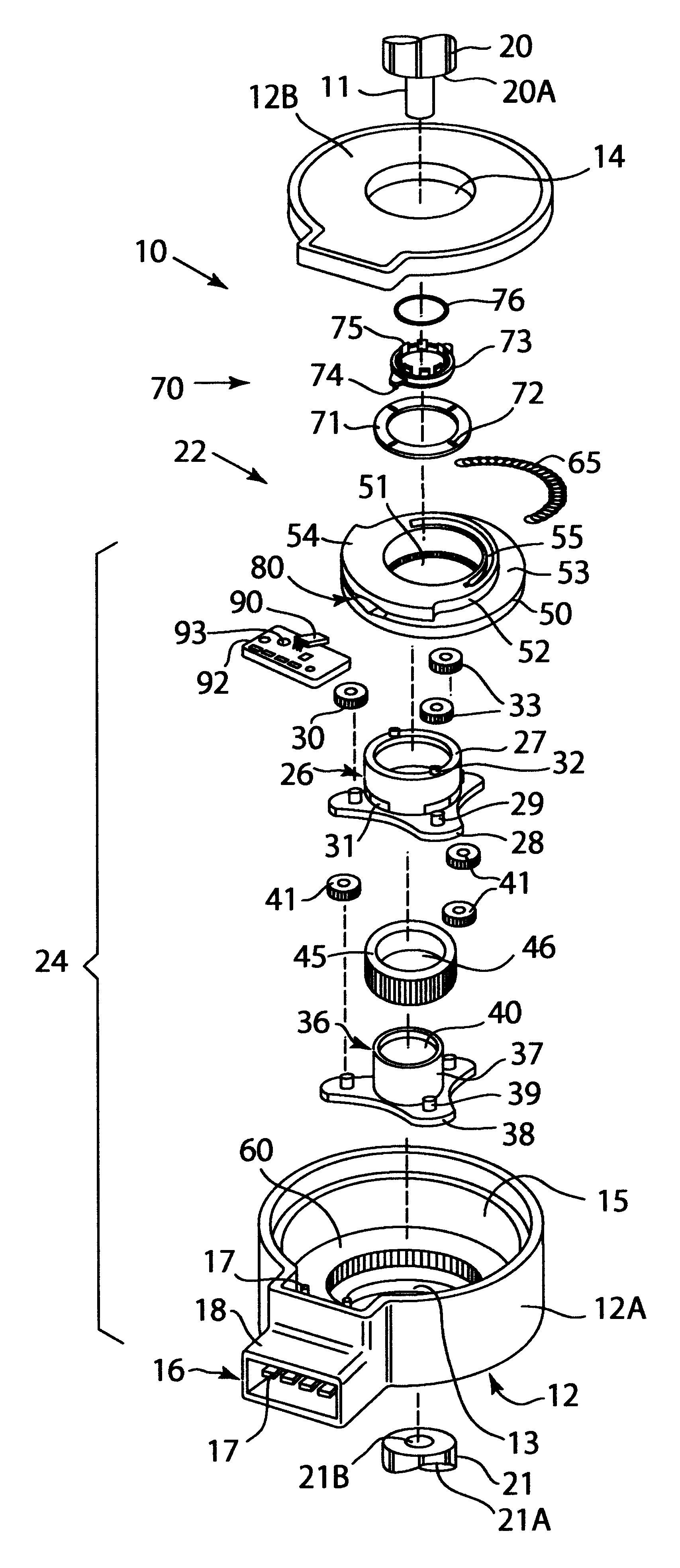
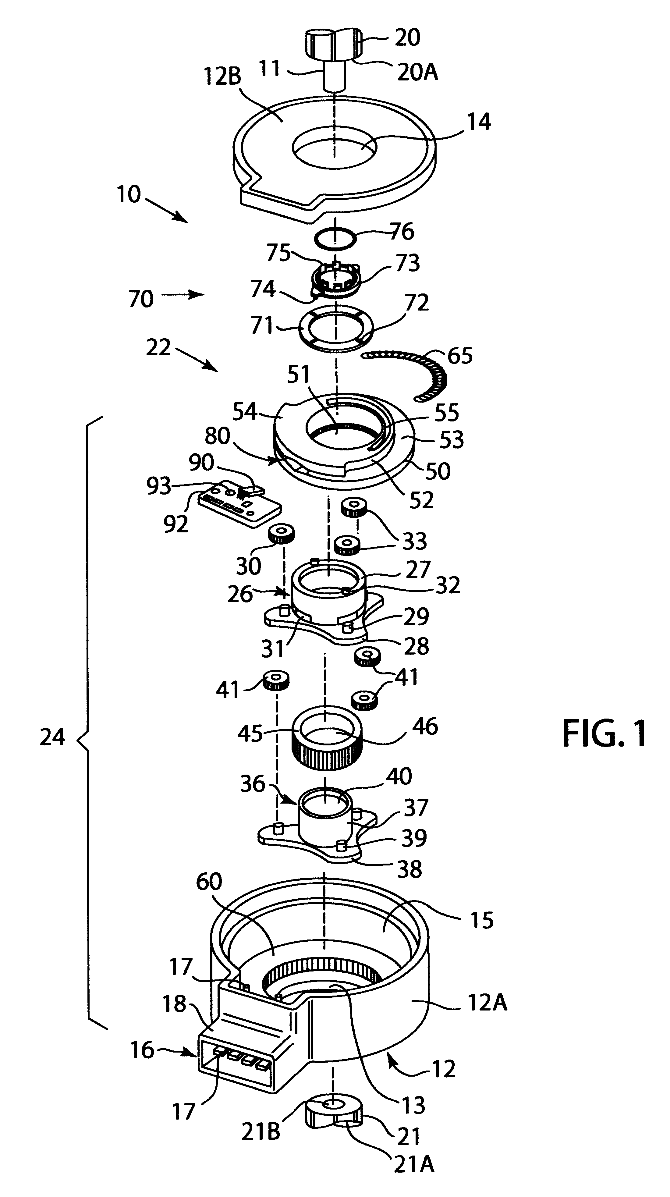
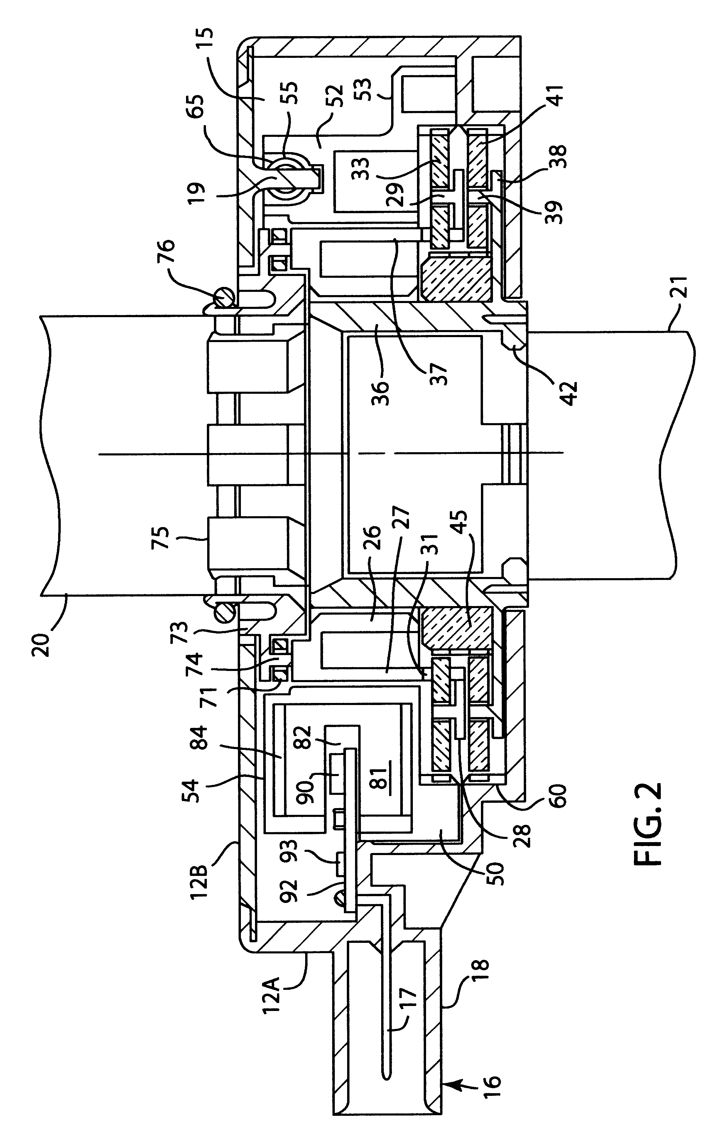
Although the illustrated embodiment discusses the use of a non-contacting sensor, one skilled in the art will realize that the preferred embodiment would work with a contacting sensor. For example, it is contemplated to place a resistor element on fin 54 and to attach a wiper to the circuit board. Alternatively, the resistor could be placed on the circuit board and the wiper on fin 54. Additionally, an optical sensor could be used or a magnetic encoder.

Although the preferred embodiment showed the use of a planetary gear assembly, It is equivalent to use other types of gear arrangements. For example, ring and pinion, worm, helical or bevel gear assemblies could be used.

In a planetary gear system, the shafts 20 and 21 would not have to be connected to the carriers. They could be connected to separate suns or separate rings.

In the preferred embodiment, one particular combination of carriers, sun gears planets and ring gears were shown. Specifically, each of the carriers was attached to...


PUM


Abstract

A sensor for measuring the relative displacement between two rotating shafts. The sensor can sense a torque applied to the steering wheel of a vehicle. The sensor has a housing that has apertures at each end. The rotating shafts pass into the housing. A sensor assembly is located in the housing and connected to the shafts. The sensor assembly generates an electrical signal that is proportional to the relative rotational displacement between the shafts. An electrical connector is located in the housing and electrically connects with the sensor assembly. The sensor assembly has a planetary gear assembly that is connected to the shafts. A variable magnetic field generator is connected to the planetary gear assembly and moves proportional to the relative rotational displacement of the shafts. A magnetic field sensor is located adjacent the variable magnetic field generator and generates the electrical signal as the variable magnetic field generator moves.

Description

1. Field of the InventionThis invention relates to sensors. In particular, there is a sensor that can measure the relative displacement between two rotating shafts. The sensor can be used to sense the amount of torque applied to a steering wheel in vehicle.2. Description of the Related ArtVarious devices and methods of dealing with the design of steering wheel sensors are known. Examples of patents related to the present invention are as follows, and each patent is herein incorporated by reference for the supporting teachings:U.S. Pat. No. 5,353,004 is a sensor for detecting steering angle.U.S. Pat. No. 5,818,038 is a steering wheel angular position sensor.U.S. Pat. No. 5,434,784 is a vehicle steering wheel position sensing apparatus.U.S. Pat. No. 5,248,939 is an apparatus for sensing the direction and speed of a steering wheel shaft using hall effect sensors in a detachable sensor mounting.U.S. Pat. No. 5,044,084 is an angle sensor element.U.S. Pat. No. 4,839,579 is a resistive ste...

Claims


Application Information

Patent Timeline
IPC IPC(8): B62D15/00B62D15/02G01L5/22G01L3/10
CPCB62D6/10G01L5/221G01L3/107B62D15/0215
Inventor SCHLABACH, ROD A.
Owner CTS CORP ELKHART
Why Eureka
Try Eureka