Mold vent

a technology of mold material and venting system, which is applied in the field of mold vent and system, can solve the problems of trapped air in the mold material, porosity or bubbles defects in the finished part, etc., and achieves the effect of convenient use and low implementation cos

Inactive Publication Date: 2002-04-09
WIEDER KLAUS A
View PDF41 Cites 83 Cited by
  • Summary
  • Abstract
  • Description
  • Claims
  • Application Information

AI Technical Summary

Benefits of technology

Each orifice of a vent is constructed to permit fluid flow of gas or vapor while preventing flow of hardenable material. Each orifice communicates with a vent passage that in turn leads to a vent passageway. So that fluid flowing through an orifice will not condense inside, each orifice has a narrow entrance adjacent the mold cavity that opens in the passage into an expansion chamber downstream. In one preferred embodiment, each orifice is oblong or slot-shaped. As a result of this construction, the venting surface area is increased, which advantageously enables atmosphere within a mold cavity to be more quickly vented permitting faster mold cycle times to be achieved.
It is an advantage of the system and method of the invention that it can be used to vent and introduce a fluid during the same molding cycle.

Problems solved by technology

If the trapped air is not vented from the mold cavity quickly enough or not vented at all, the finished part can have defects.
For example, trapped air can impart knit lines or poor surface cosmetics in the exterior of the finished part.
Even worse, gases from the mold material can migrate into the mold material creating porosity or bubbles in the finished part.
Conversely, when defects occur because venting is poor or virtually nonexistent, the rate of injecting the hardenable mold material into the cavity is often significantly reduced rather dramatically slowing production.
Thus, not only can venting related problems lead to defective finished parts that must be scrapped, these problems can also significantly reduce production, which is also costly.
The reason that venting-related defects occur so frequently is that venting is not well understood and that venting is neither cheap nor easy.
Unfortunately, machined-in-place vents, such as core pin vents, ejector pin vents, perimeter vents, and circumference vents, can have problems.
One problem that commonly results from machined vents is that volatile gases from the mold material can condense at the narrowest portion of the vent, typically the orifice or passage, plugging the vent.
If the condensate doesn't completely plug the vent, it can partially obstruct the vent, rendering the vent effectively useless and requiring the vent to be periodically cleaned.
Even if not rendered useless, a partially plugged vent can lead to one or more of the vent-related molding problems previously discussed.
Another problem with machining these vents is that if precise tolerances are not maintained during machining, the resulting vent will not perform properly and may have to be filled and re-machined.
For example, if an orifice is off by as little as two one-thousandths of an inch (0.002"), the vent will either be too large and allow mold material to enter the orifice plugging the vent or be too narrow leading to one or more of the above-identified vent-related problem.
Unfortunately, the sintering process creates uneven vent surfaces, has pores that are not parallel, and has corners.
Another type of vent, a parting line vent, typically suffers from other problems.
For example, the flowing molding material can impact against the interior surface adjacent the parting line vent with such force that it can dent or peen the interior surface.
This can lead to surface irregularities in the finished part.
If the dents extend too far into the vent, the mold material can enter the vent creating unwanted flash that must be trimmed.
Of course, any additional operation that must be performed costs money and requires labor, both of which are undesirable.

Method used


Image

  • Mold vent
  • Mold vent
  • Mold vent

Examples


Embodiment Construction

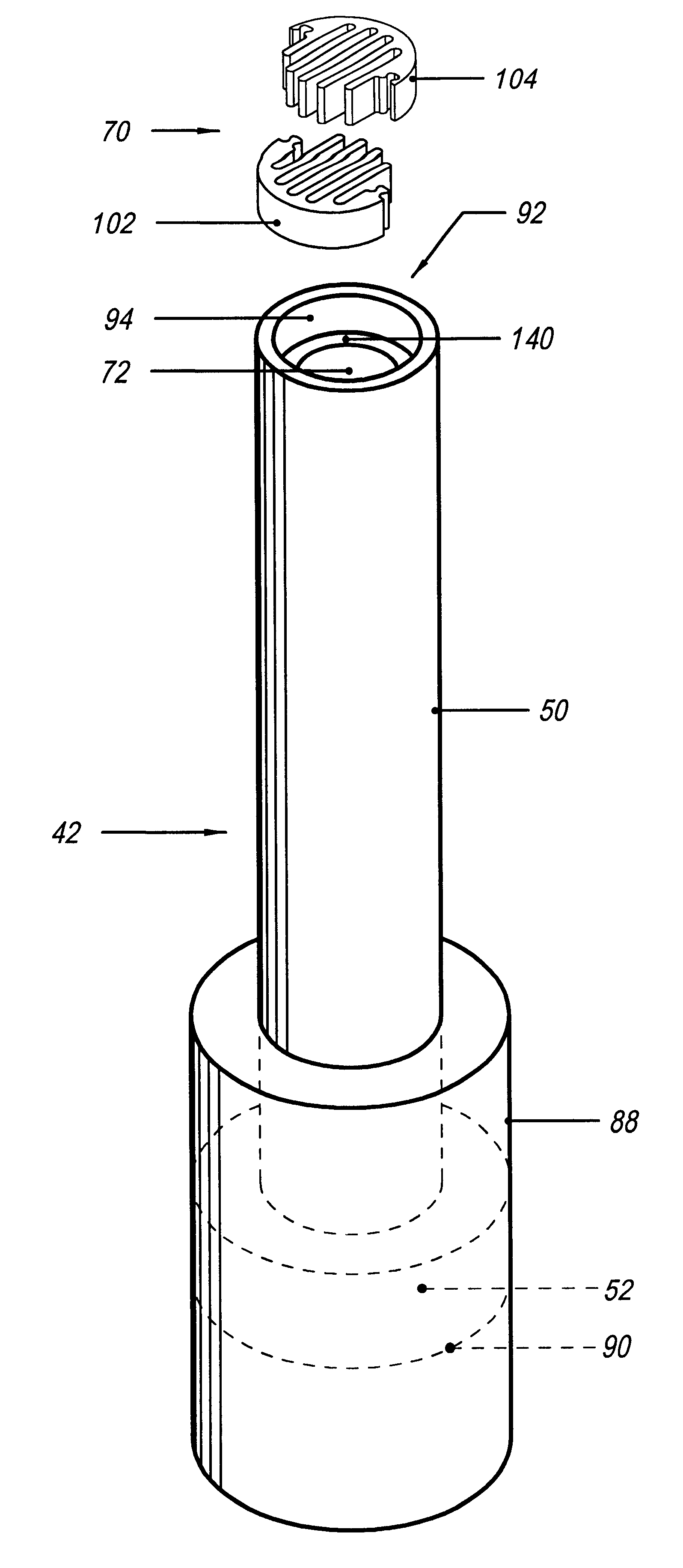
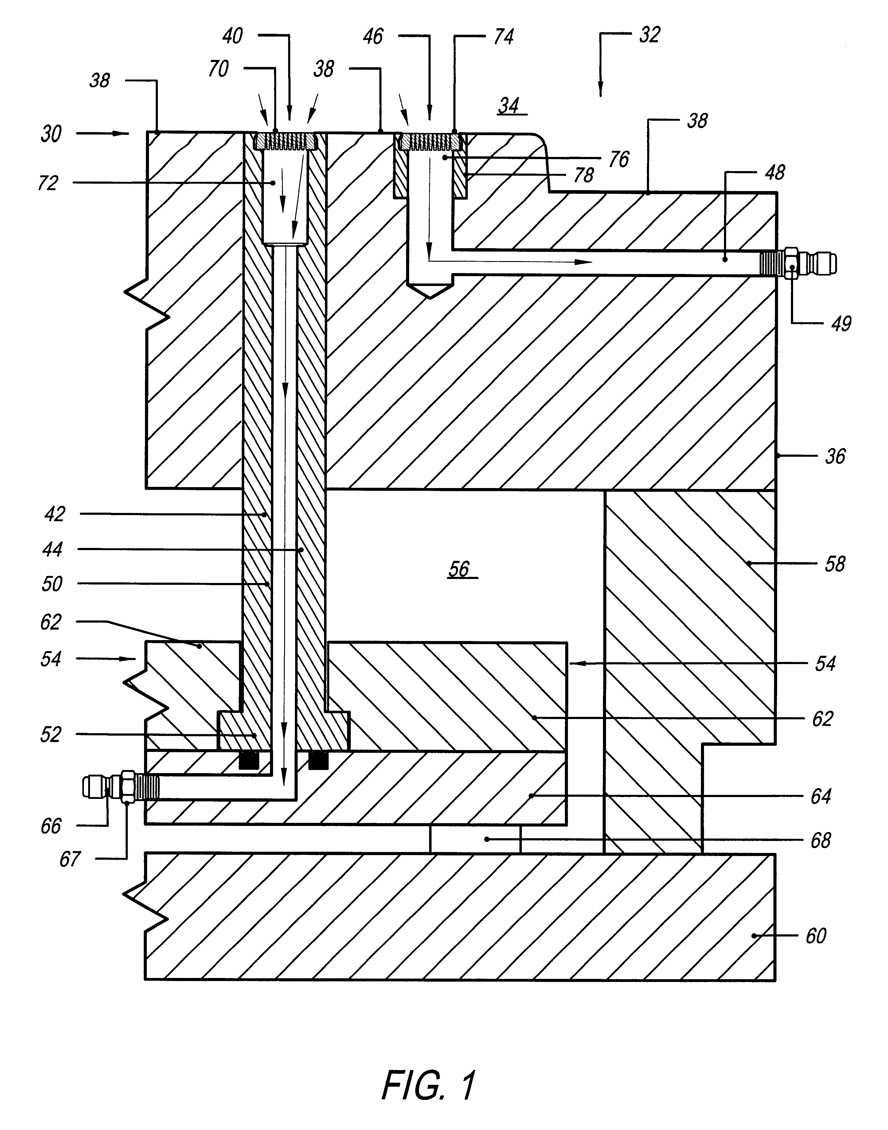
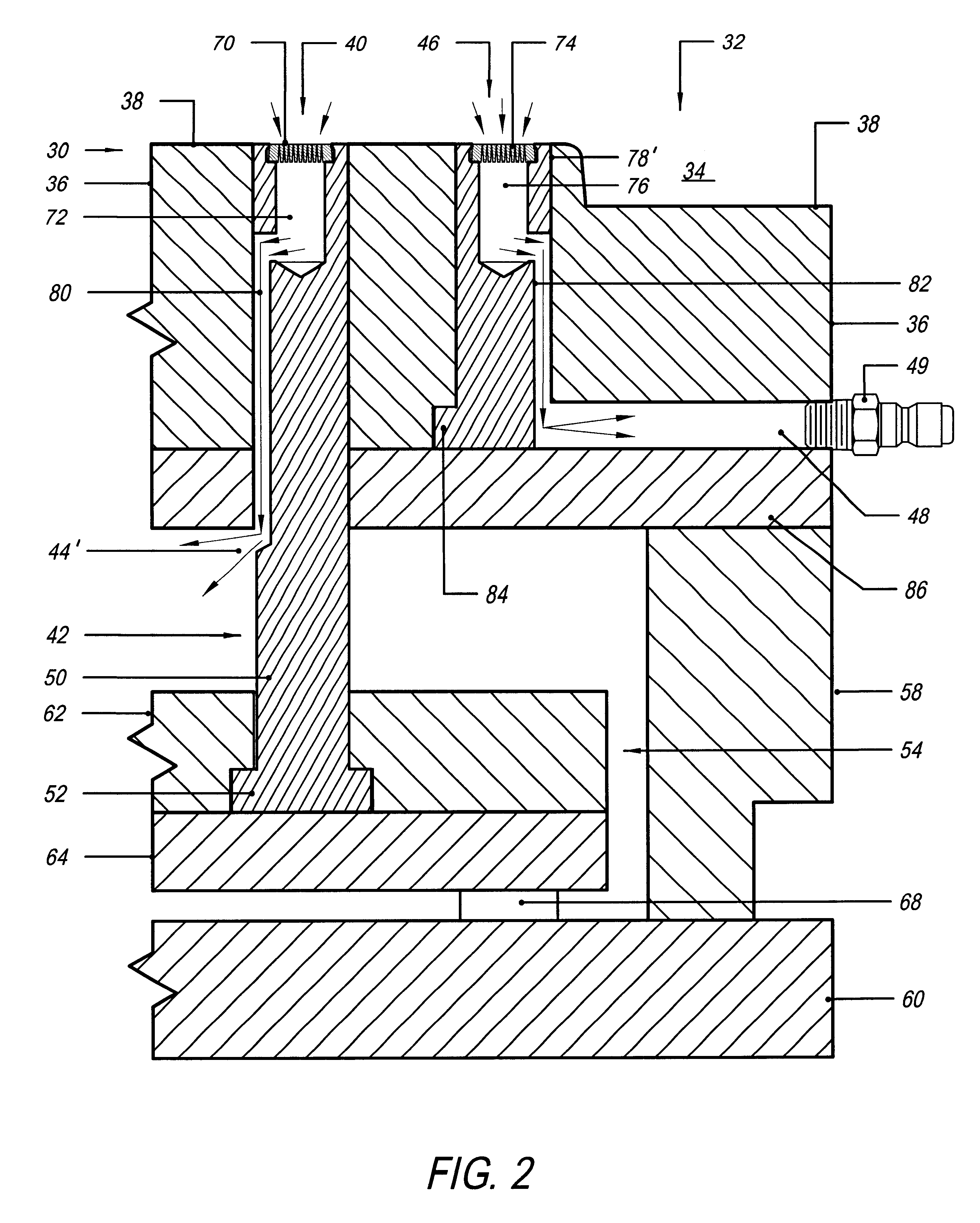
FIG. 1 illustrates one portion 30 of a mold 32, preferably a mold half, having a mold cavity 34 in which a hardenable or moldable material is introduced in a flowable state, preferably under pressure. The mold half 30 is comprised of an upper plate 36 with a mold cavity surface 38 that preferably is contoured to impart a desired shape to the moldable material when the moldable material solidifies or hardens.

To facilitate evacuation of air and other gases in the mold cavity, the mold half 30 has at least one vent. For example, the mold half 30 shown in FIG. 1 has a first vent 40 carried by a pin 42. Such a pin 42 can be a reciprocable ejector pin or core pin that can include a vent passageway 44. The mold half 30 is shown equipped with a second stationary vent 46 disposed in the mold cavity surface 38 that communicates with a vent passageway 48 in plate 36.

During molding, another portion of the mold 32 mates with the mold half 30 and a hardenable material is introduced into the mold ...


PUM

PropertyMeasurementUnit
widthaaaaaaaaaa
widthaaaaaaaaaa
angleaaaaaaaaaa

Abstract

A vent, system and method for controlling flow of fluid into and out of a mold cavity. The vent has a plurality of passages that each have narrow oblong slot-shaped openings in the mold cavity and which each expand in size in a direction leading away from its opening. The vent preferably is an insert that comprises a grate with at least a plurality of vent slots. The grate preferably is formed of two halves with fingers that interleave to form the slots when assembled. The grate preferably is discharge machined from disc-shaped blanks cut from elongate stock made a material that preferably is non-porous and smooth. The grate can be mounted in a pocket in the mold cavity or carried by a movable pin. A system uses valving and a source of fluid and, if needed, a source of vacuum to help facilitate venting by drawing atmosphere out of the cavity during molding. The system can also be used to introduce fluid through a vent such as for foaming moldable material in the cavity. The system can also be used to introduce a heat transfer medium into the mold cavity. The system can also be used to accelerate venting during one part of a mold cycle and then introduce fluid into the cavity during the same cycle.

Description

The present invention relates to a vent, system and method for a mold and more particularly to a vent insert, method of making the insert, and system and method for controlling vent flow to and from the mold.During molding, the atmosphere inside the mold cavity must somehow be vented from the mold cavity to avoid the air in the mold cavity, along with gases from the mold material, from causing defects in the part being molded. If the trapped air is not vented from the mold cavity quickly enough or not vented at all, the finished part can have defects. For example, trapped air can impart knit lines or poor surface cosmetics in the exterior of the finished part. Even worse, gases from the mold material can migrate into the mold material creating porosity or bubbles in the finished part.Venting also has an impact on how fast parts can be molded. It stands to reason that the faster air and other gases in the mold cavity can be vented from the cavity, the faster the mold cavity can be fi...

Claims


Application Information

Patent Timeline
Patent Type & Authority Patents(United States)
IPC IPC(8): B22C9/06B22D17/00B22D17/14B29C33/10B29C45/17B29C45/34
CPCB22C9/067B22D17/145B29C33/10B29C45/34B29C45/1703Y10S425/06Y10S425/812
Inventor WIEDER, KLAUS A.
Owner WIEDER KLAUS A
Why Eureka
Try Eureka