

Gas sealing apparatus for variable capacity supercharger
a supercharger and gas sealing technology, which is applied in the direction of machines/engines, stators, liquid fuel engines, etc., can solve the problem of not being able to incorporate a piston ring system
- Summary
- Abstract
- Description
- Claims
- Application Information
AI Technical Summary
Problems solved by technology
Method used
Image

Examples
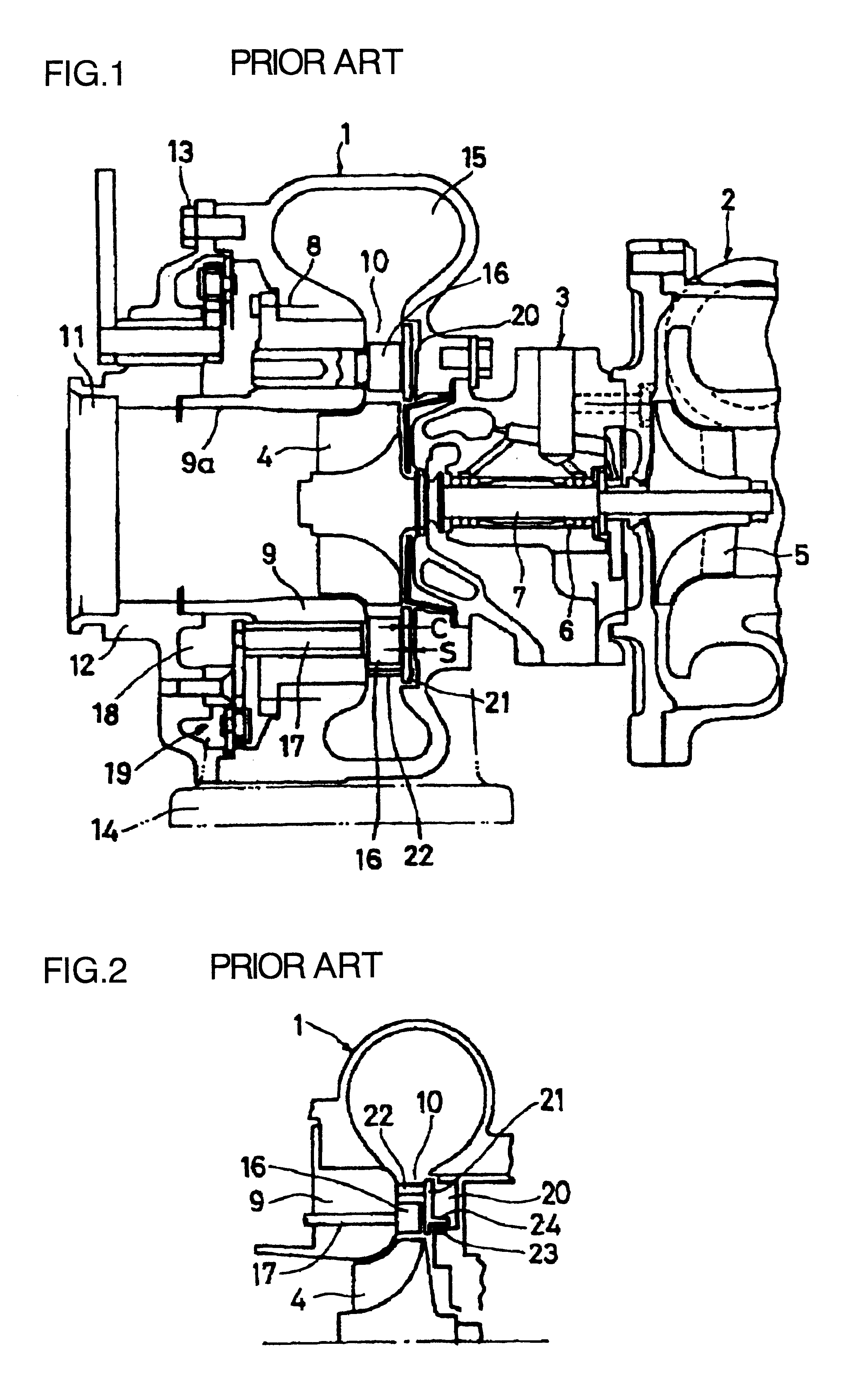
first embodiment
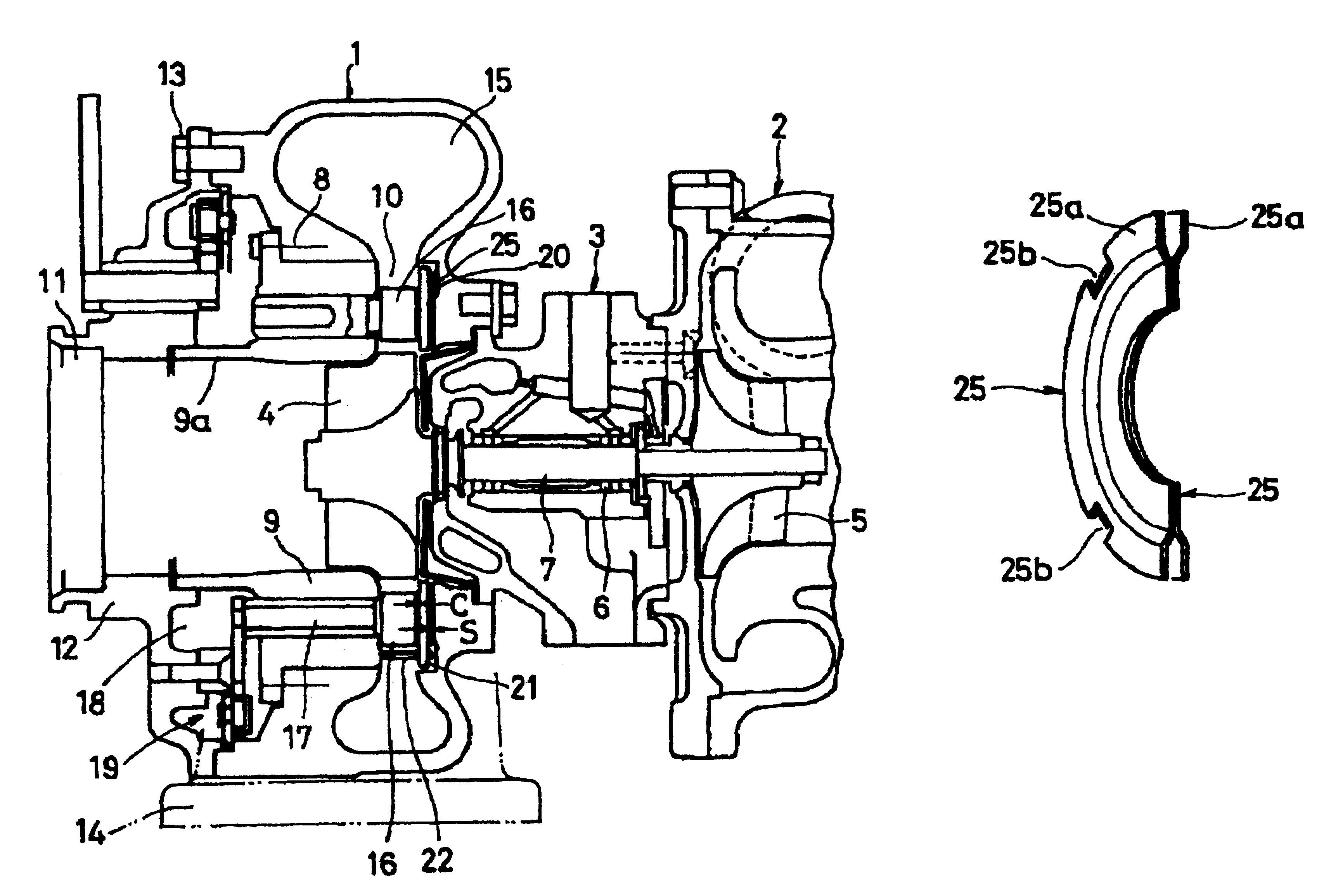
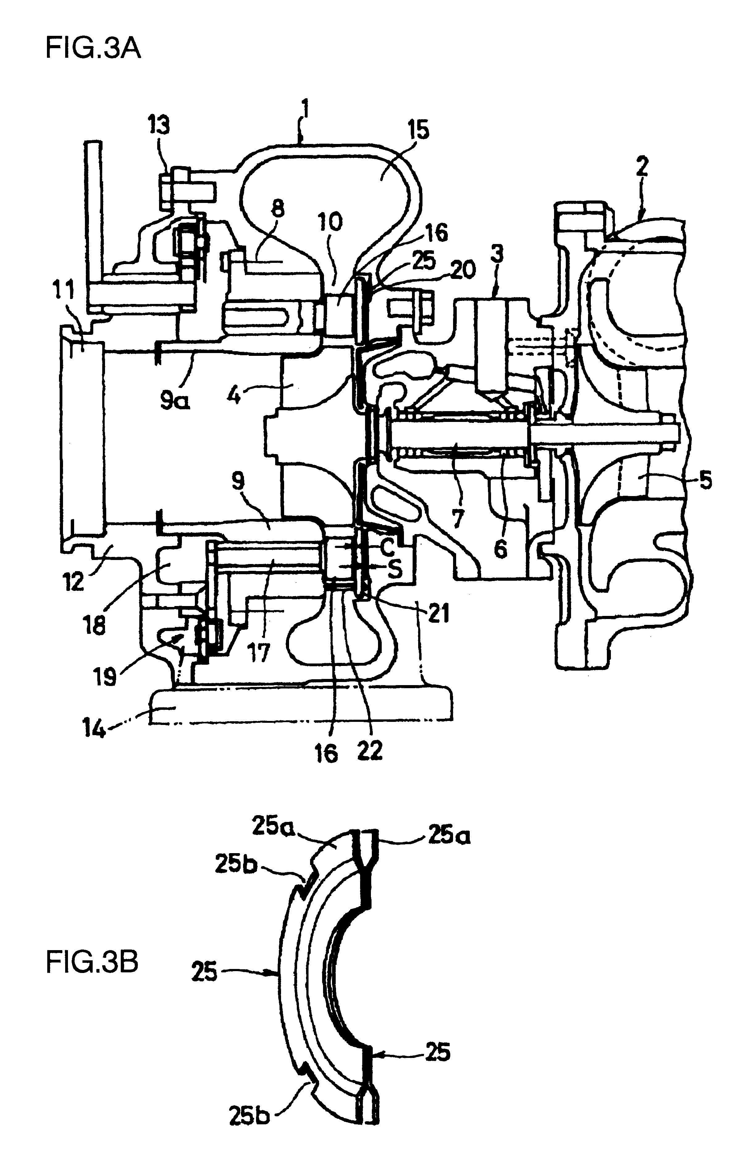
FIGS. 3A and 3B show the present invention. In these figures, the gas sealing apparatus for a variable capacity supercharger according to the present invention is provided with annular turbine shroud 9 disposed on the inner periphery of turbine housing 1 on the opposite side to bearing housing 3; annular channel 10 is formed between surfaces of the outer periphery of aforementioned turbine shroud 9 and the inner periphery of turbine housing 1 on the side of bearing housing 3; a large number of nozzle vanes 16 are arranged in above-mentioned annular channel 10 in such a manner that the opening and closing angles of the vanes can be adjusted by rotating operating shaft 17 which penetrates the outer periphery of aforementioned turbine shroud 9; annular recess 20 is formed on the surface of the annular channel of above-mentioned turbine housing 1; ring-shaped clearance control plate 21 is arranged in and fixed at above-mentioned recess 20 by means of mounting shaft 22 supported by turbi...
second embodiment
Next, FIG. 4 shows the gas sealing apparatus according to the present invention, whereby even when turbine housing 1 thermally deforms, the turbine shroud 9 side is protected from any direct effects. More explicitly, in the same configuration as shown in FIGS. 3A and 3B, above-mentioned turbine shroud 9 is structured in such a manner that the shroud is inserted in turbine housing 1 in the axial direction, and gas discharge channel 9a on the inner periphery of aforementioned turbine shroud 9 is mounted to and fixed at cover 12 on the outer surface of turbine housing 1, using fixing screw 26; in addition, seal ring 27 in a shape similar to a piston ring is equipped in the axial insert portion between above-mentioned turbine shroud 9 and turbine housing 1.
In the configuration of the embodiment shown in FIG. 4, because turbine shroud 9 is isolated from turbine housing 1, any thermal deformation of turbine housing 1 no longer directly affects turbine shroud 9. As a result, the thermal de...
PUM
 Abstract
Description
Claims
Application Information