Apparatus and method for post weld laser release of gas build up in a gmaw weld

a technology of gas build-up and laser release, which is applied in the direction of welding/cutting media/materials, welding apparatus, manufacturing tools, etc., can solve the problems of degrading the quality of welds, difficult to galvanize materials after welding, and difficult process of welding coated materials

Inactive Publication Date: 2013-04-11
LINCOLN GLOBAL INC
View PDF12 Cites 12 Cited by
  • Summary
  • Abstract
  • Description
  • Claims
  • Application Information

AI Technical Summary

Benefits of technology

[0006]Embodiments of the present invention include equipment and methods of welding at least one work piece with an arc welding process such that a liquid weld puddle is created from the at least one work piece and the welding is being performed in a travel direction. Also, an energy beam is directed to a surface of

Problems solved by technology

It is very difficult to galvanize materials after they are welded in place and as such most steel components are galvanized prior to welding.
However, welding coated materials can be a difficult process because the coating can interfere with the welding

Method used


Image

  • Apparatus and method for post weld laser release of gas build up in a gmaw weld
  • Apparatus and method for post weld laser release of gas build up in a gmaw weld
  • Apparatus and method for post weld laser release of gas build up in a gmaw weld

Examples


Embodiment Construction

[0022]Exemplary embodiments of the invention will now be described below by reference to the attached Figures. The described exemplary embodiments are intended to assist the understanding of the invention, and are not intended to limit the scope of the invention in any way. Like reference numerals refer to like elements throughout.

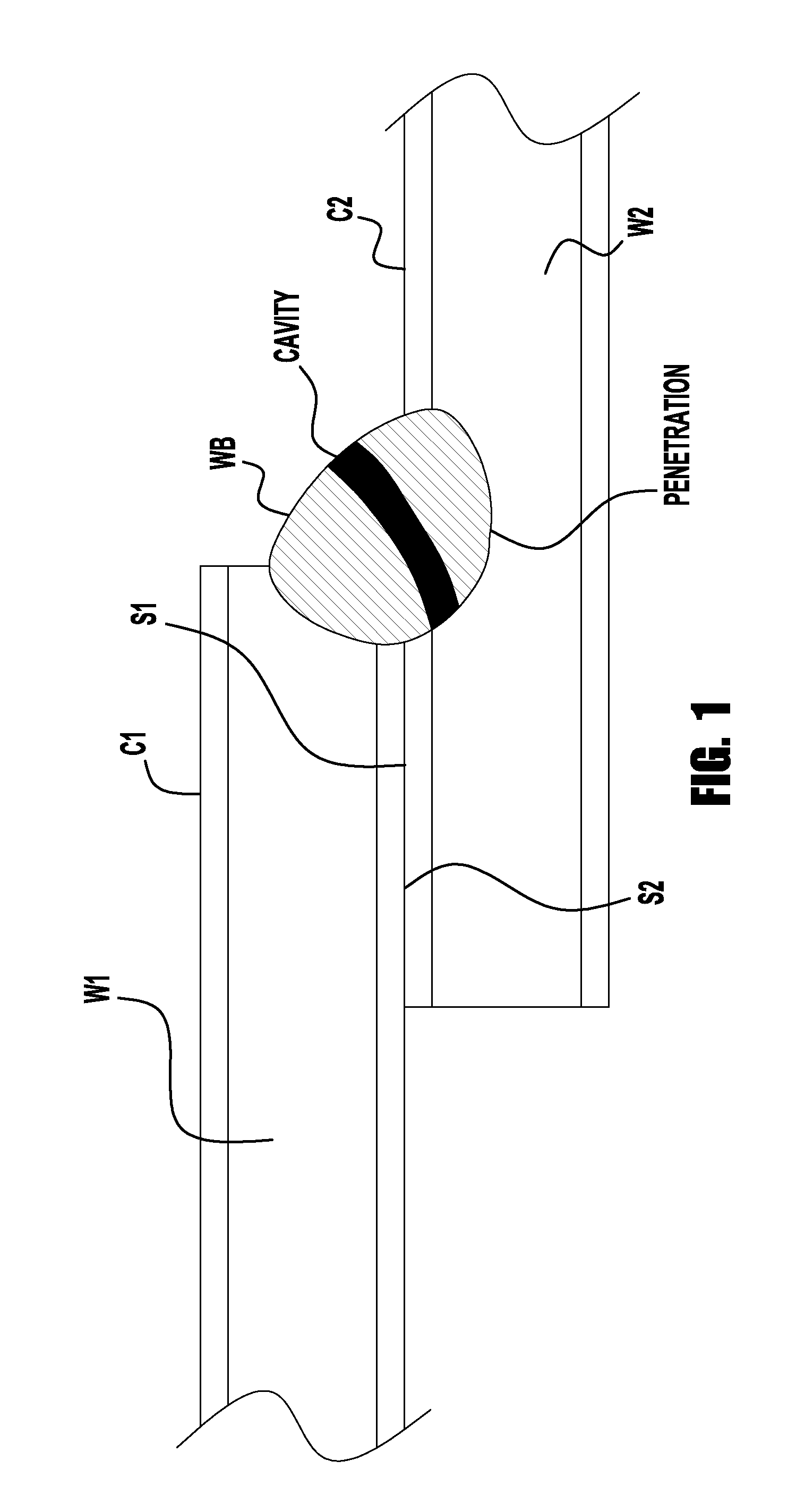
[0023]FIG. 1 depicts a typical welded lap joint where a first work piece W1 is placed partially on top of a second work piece W2 and the two are welded with a weld bead WB. In the welding industry, this type of connection is commonly referred to as a lap joint. Lap joints are common in the automotive industry. In addition to lap joints, embodiments of the present invention can weld multiple different types of joints as well, including: fillet joints, joggle joints, butt joints, etc. As shown in FIG. 1, at least one of the work pieces has a coating C1 / C2 on the surfaces to be welded, where the coatings have a different material composition than the work pie...


PUM

PropertyMeasurementUnit
Fractionaaaaaaaaaa
Fractionaaaaaaaaaa
Fractionaaaaaaaaaa

Abstract

A system and method is provided where a work piece is welded at high speeds with minimal porosity and spatter. In embodiments, the work piece is welded with an arc welding process to create a weld puddle and the weld puddle is irradiated by a energy beam downstream of the arc welding operation, such that high welding speeds are attained. The high energy heat source is positioned downstream of the welding operation to input energy into the weld puddle to change its shape or characteristics to optimize bead shape and/or bead quality.

Description

PRIORITY[0001]The present invention is a continuation-in-part of U.S. patent application Ser. No. 13 / 267,641, filed on Oct. 6, 2011, the disclosure of which is incorporated herein by reference, in its entirety.BACKGROUND OF THE INVENTION[0002]1 Field of the Invention[0003]Systems and methods of the present invention relate to welding and joining, and more specifically to the welding and joining of coated materials.[0004]2. Description of the Related Art[0005]Many welded structures are used in environments which require surface coatings to prevent corrosion. For example, the deposition of zinc on steel (through galvanization or galvannealing) is commonly used to protect the steel from corrosion when the steel is exposed to the environment. It is very difficult to galvanize materials after they are welded in place and as such most steel components are galvanized prior to welding. However, welding coated materials can be a difficult process because the coating can interfere with the we...

Claims


Application Information

Patent Timeline
IPC IPC(8): B23K9/00
CPCB23K2203/04B23K26/367B23K26/0066B23K9/025B23K9/16B23K9/23B23K26/0009B23K2201/34B23K2201/18B23K26/352B23K26/364B23K2103/50B23K26/0006B23K2103/04B23K2101/18B23K2101/34B23K2103/05
Inventor DENNEY, PAUL E.PETERS, STEVEN R.
Owner LINCOLN GLOBAL INC
Why Eureka
Try Eureka