High deposition rate thermal spray using plasma transferred wire arc

a plasma transfer and thermal spray technology, applied in plasma welding apparatus, plasma technique, manufacturing tools, etc., can solve the problems of inability to predict the occurrence of such instabilities, lack of robustness, and melted metal spitting rather than fine particles

Inactive Publication Date: 2002-04-16
FORD GLOBAL TECH LLC
View PDF4 Cites 56 Cited by
  • Summary
  • Abstract
  • Description
  • Claims
  • Application Information

AI Technical Summary

Problems solved by technology

Existing torches and associated apparatus of the prior art, used to generate the plasma transferred wire arc, lack robustness and are sensitive to instabilities in process parameters resulting i

Method used


Image

  • High deposition rate thermal spray using plasma transferred wire arc
  • High deposition rate thermal spray using plasma transferred wire arc
  • High deposition rate thermal spray using plasma transferred wire arc

Examples


Embodiment Construction

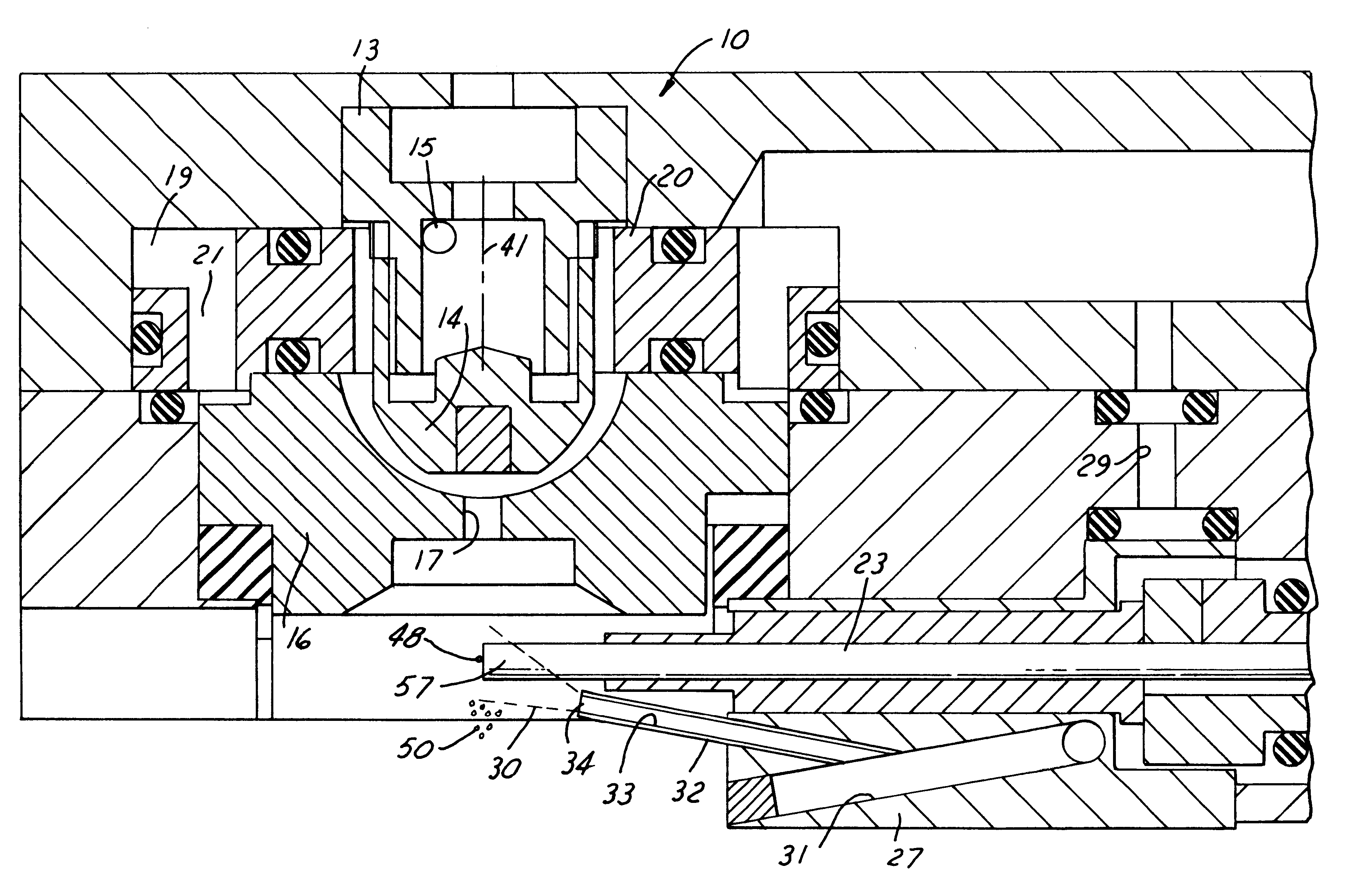
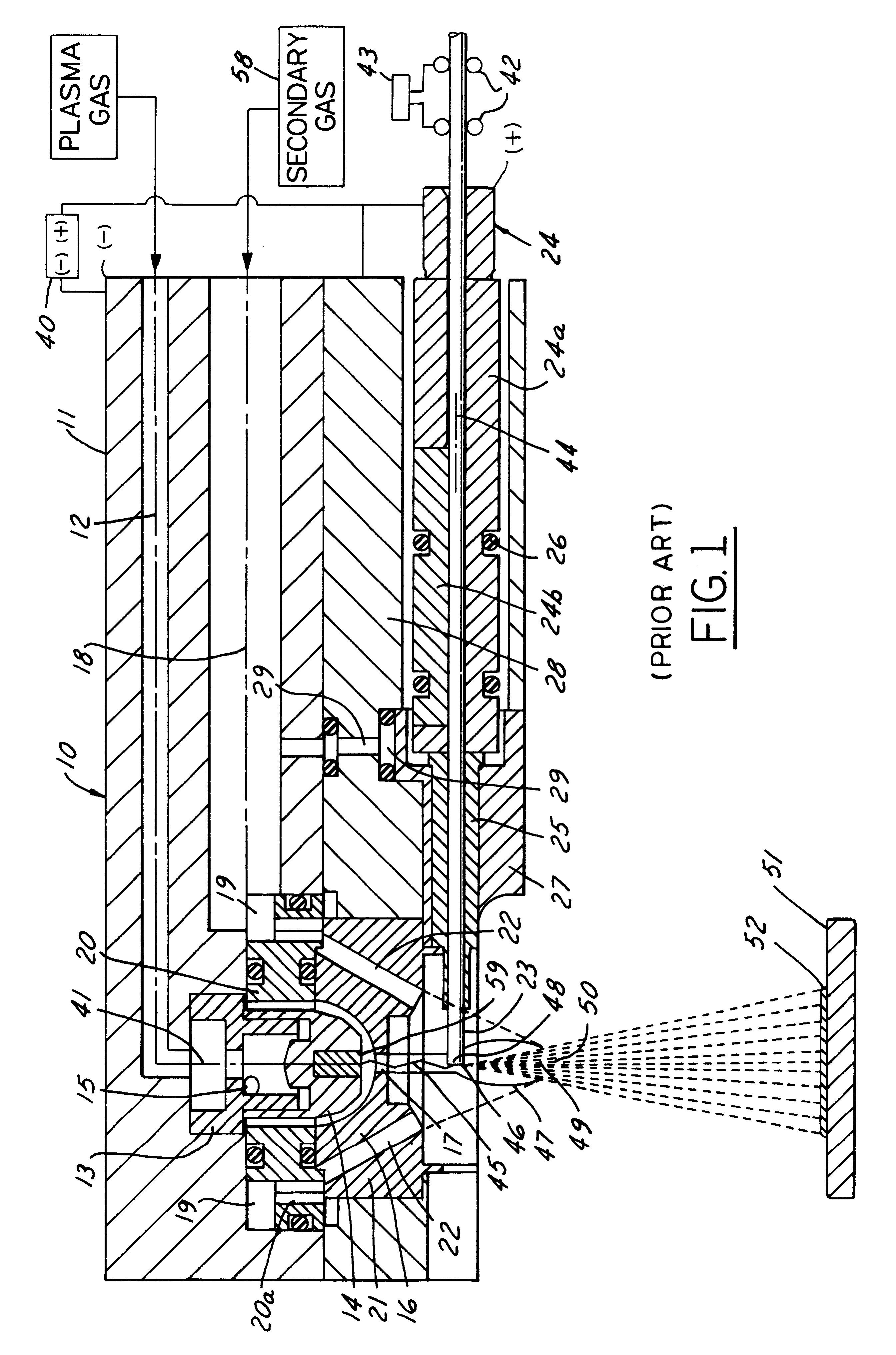
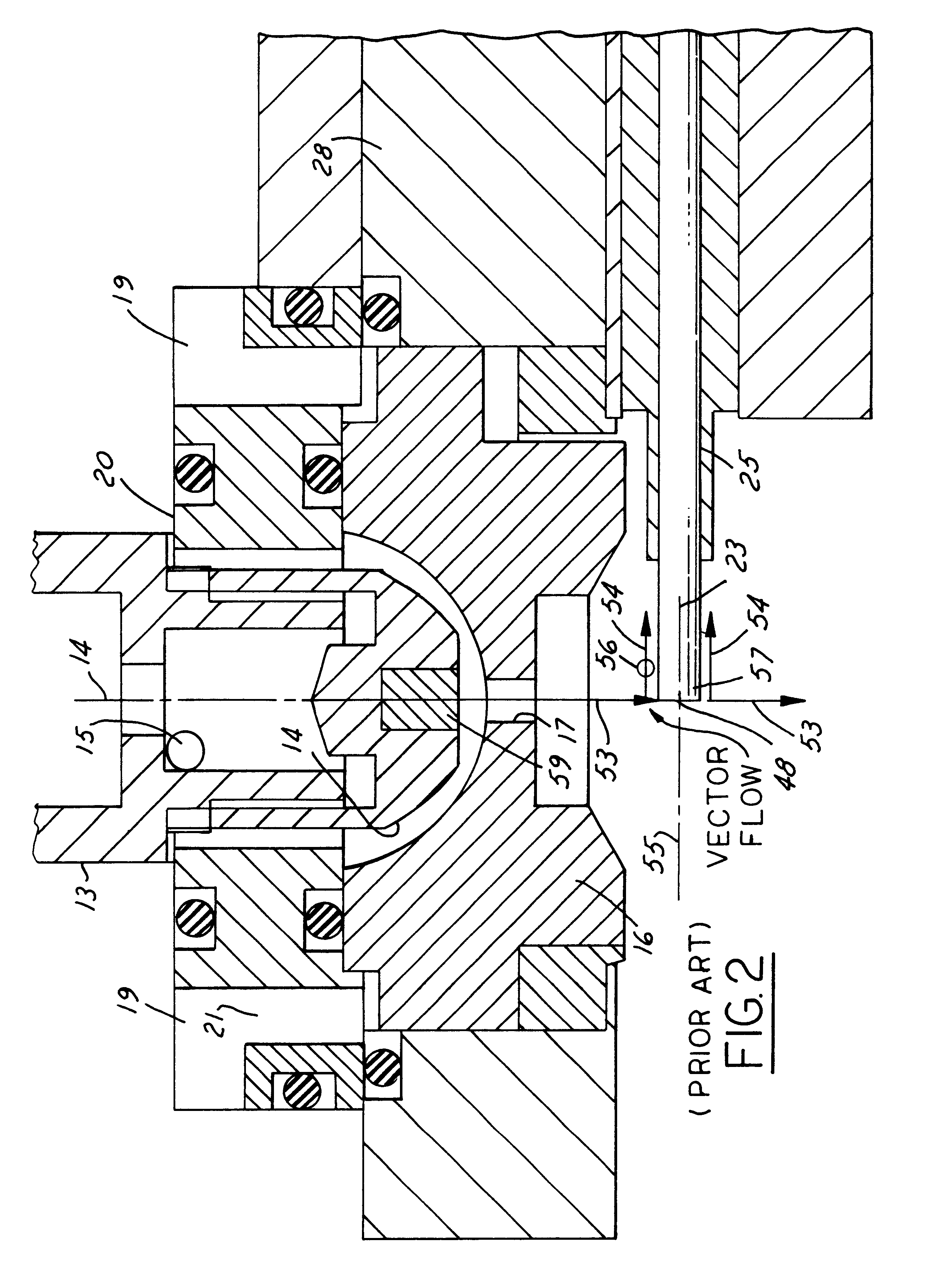
The transferred plasma-arc torch assembly 10 consists of a torch body 11 containing a plasma gas port 12 and a secondary gas port 18; the torch body 11 is formed of an electrically conductive metal. The plasma gas is connected by means of port 12 to a cathode holder 13 through which the plasma gas flows into the inside of the cathode assembly 14 and exits through tangential ports 15 located in the cathode holder 13. The plasma gas forms a vortex flow between the outside of the cathode assembly 14 and the internal surface of the pilot plasma nozzle 16 and then exits through the constricting orifice 17. The plasma gas vortex provides substantial cooling of the heat being dissipated by the cathode function.

Secondary gas enters the torch assembly through gas inlet port 18 which directs the secondary gas to a gas manifold 19 (a cavity formed between baffle plate 20 and torch body 11 and thence through bores 20a into another manifold 21 containing bores 22). The secondary gas flow is unif...


PUM

PropertyMeasurementUnit
Timeaaaaaaaaaa
Timeaaaaaaaaaa
Pressureaaaaaaaaaa

Abstract

Method of thermally depositing metal at increased rates onto a target surface, comprising: establishing and operating a high velocity plasma transferred wire arc between a cathode and the free-end of a consumable wire electrode, the energy of such plasma and arc being sufficient to not only melt and atomize the free-end of the wire into metal particles, but also project the particles as a column onto the target surface at an enhanced deposition rate for continuous periods in excess of 50 hours; surrounding the plasma and arc with high velocity and high flow gas streams that converge beyond the intersection of the wire free-end with the plasma-arc to limit turbulence of the plasma-arc, avoid direct impingement with the wire and assist the projection of the particles to the target surface; and impinging a low velocity gas flow along the axis of the advancing wire to counteract any destabilizing fluid dynamic forces attempting to move melted particles back along the wire away from the wire free end.

Description

1. Technical FieldThis invention relates to electric arc spraying of metals and, more particularly, to a plasma-arc transferred to a single wire tip that is fed continuously into the plasma-arc.2. Discussion of the Prior ArtAs disclosed in earlier U.S. patents by the co-inventors herein, plasma transferred wire arc is a thermal spray process which melts a continuously advancing feedstock material (usually in the form of a metal wire or rod) by using a constricted plasma-arc to melt only the tip of the wire or rod (connected as an anodic electrode); the melted particles are then propelled to a target. The plasma is a high velocity jet of ionized gas which is desirably constricted and focused about a linear axis by passing it through a nozzle orifice downstream of a cathode electrode; the high current arc, which is struck between the cathodic electrode and the anodic nozzle, is transferred to the wire tip maintained also as an anode. The arc provides the necessary thermal energy to co...

Claims


Application Information

Patent Timeline
IPC IPC(8): C23C4/12
CPCB05B7/224C23C4/127C23C4/125C23C4/131C23C4/134
Inventor MARANTZ, DANIEL RICHARDKOWALSKY, KEITH ALANCOOK, DAVID JAMESGARGOL, LARRY GERALD
Owner FORD GLOBAL TECH LLC
Why Eureka
Try Eureka