Isolated converter

a converter and converter technology, applied in the direction of fixed transformers, mutual inductances, fixed transformers, etc., can solve the problems of the total size of the isolated converter, the difficulty in reducing the size of the multilayer circuit board, and the breakdown of the primary and secondary circuits

Inactive Publication Date: 2002-04-16
MURATA MFG CO LTD
View PDF2 Cites 16 Cited by
  • Summary
  • Abstract
  • Description
  • Claims
  • Application Information

AI Technical Summary

Problems solved by technology

As a result, an electrical breakdown occurs between the primary and secondary circuits.
Because of the necessity of the large isolation space between the primary and secondary sides of the multilayer sheet transformer 1, it is difficult to reduce the size of the multilayer circuit board 4 and thus the total size of the isolated converter.
This also makes it difficult to reduce the size of the multilayer circuit board 4 and the total size of the isolated converter.
Another problem in the conventional structure described above is that the coil pattern 6a on the outer surface of the top layer and the coil pattern 6b on the outer surface of the bottom layer may e electrically connected to each other via the E-shaped core members 11a and 11b and thus the primary coil and the secondary coil may be electrically connected to each other.

Method used


Image

  • Isolated converter
  • Isolated converter
  • Isolated converter

Examples


Embodiment Construction

Embodiments of the present invention are described below with reference to the accompanying drawings. In the embodiments described below, parts similar to those of the conventional isolated converter described above are denoted by similar reference numerals, and they are not described in further detail herein.

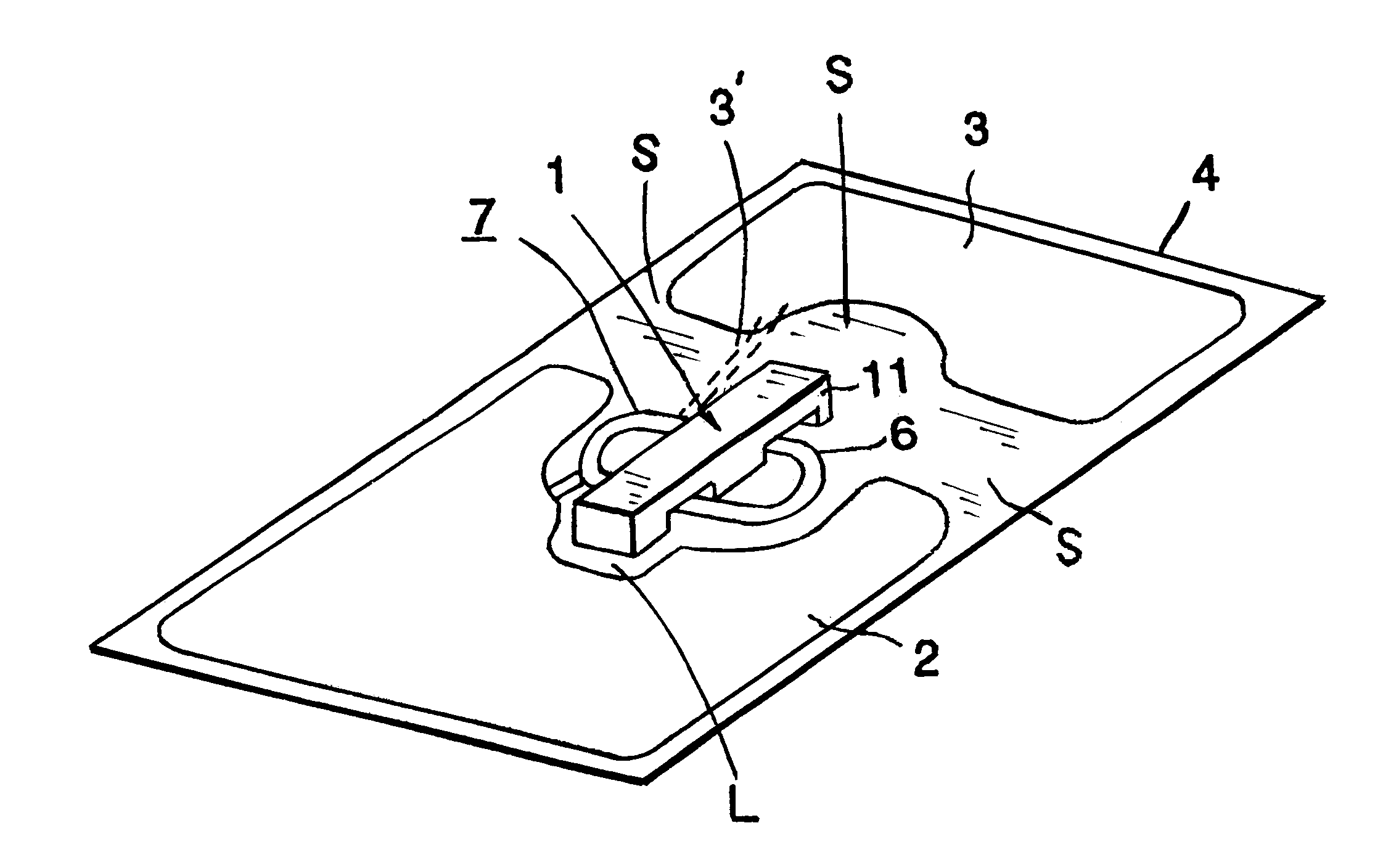
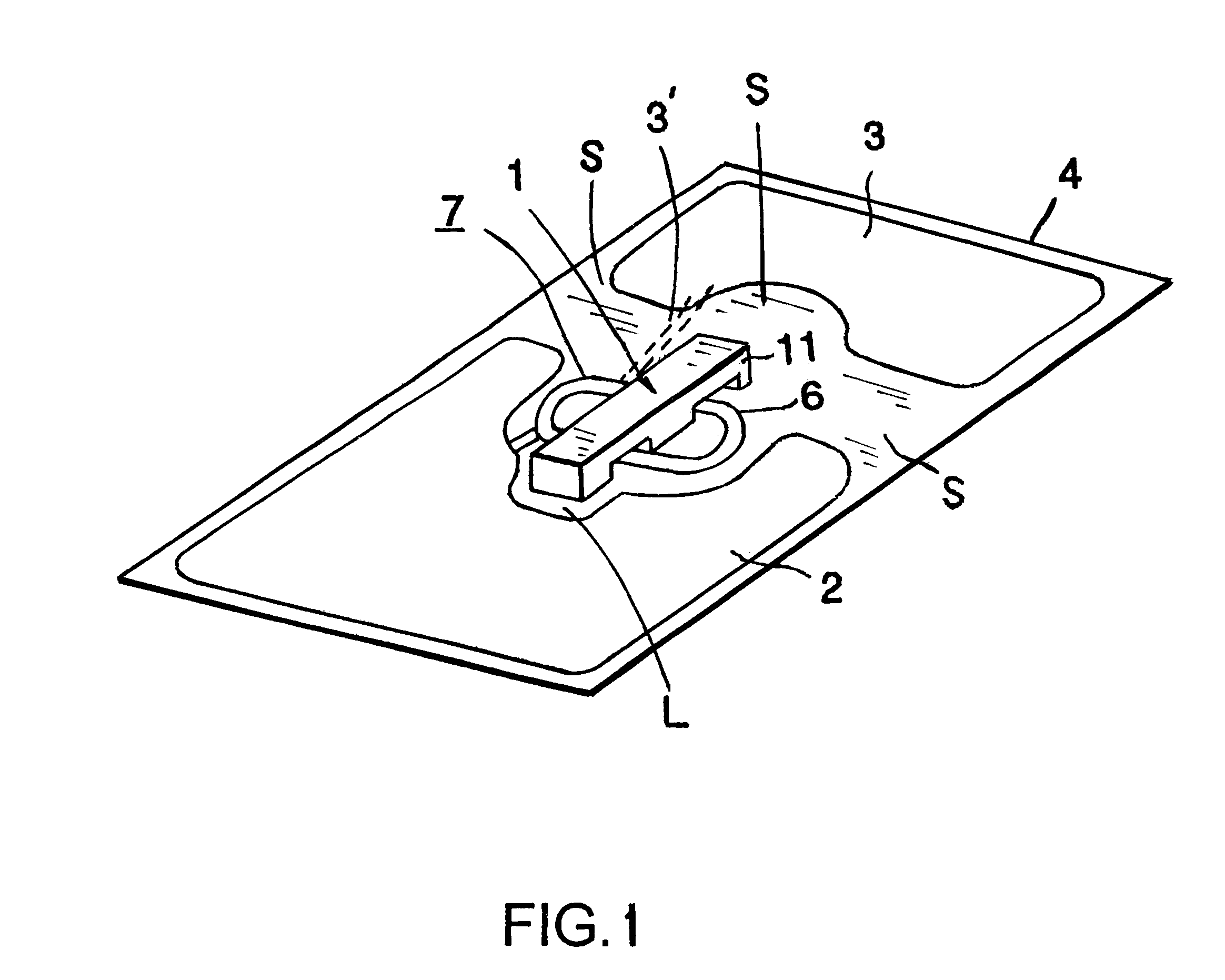
The isolated converter disclosed herein according to an embodiment of the present invention includes, as with the conventional isolated converter described above, a multilayer sheet transformer 1, a primary-side circuit 2 connected to a primary coil of the multilayer sheet transformer 1, and a secondary-side circuit 3 connected to a secondary coil of the multilayer sheet transformer 1. However, the isolated converter according to the present embodiment is different from the conventional isolated converter in that it has a novel structure which allows a reduction in the size of the isolated converter and reduces the advance of electrical breakdown.

That is, in the present embodim...


PUM

PropertyMeasurementUnit
areaaaaaaaaaaa
voltageaaaaaaaaaa
sizeaaaaaaaaaa

Abstract

An isolated converter with a reduced size is disclosed. A small-sized multilayer sheet transformer includes a multilayer circuit board composed of a plurality of sheet substrates, coil patterns of primary and secondary coils disposed coaxially on the sheet substrates, and a core member disposed in a coil pattern unit formed of the coil patterns. In this multilayer sheet transformer, a coil pattern formed on the outer surface of the top layer and a coil pattern formed on the outer surface of the bottom layer are for the same coil on either the primary or secondary side. In the case where the coil patterns formed on the outer surfaces of the top and bottom layers of the multilayer sheet transformer are for the primary coil, an isolation gap is formed between the multilayer sheet transformer and a circuit on the secondary side to prevent an electrical breakdown between the primary and secondary sides. In the case where the coil patterns formed on the outer surfaces of the top and bottom layers of the multilayer sheet transformer are for the secondary coil, an isolation gap is formed between the multilayer sheet transformer and a circuit on the primary side to prevent an electrical breakdown between the primary and secondary sides.

Description

1. Field of the InventionThe present invention relates to an isolated converter for use in a switching power supply or the like.2. Description of the Related ArtAn isolated converter (such as a DC-DC converter and isolated AC-DC converter) used in a switching power supply or the like is formed of a transformer, a primary-side circuit connected to a primary coil of the transformer, and a secondary-side circuit connected to a secondary coil of the transformer such that power supplied to the primary-side circuit is transformed in terms of voltage by the transformer and a resultant voltage is output from the secondary-side circuit.In some cases, when the isolated converter is used in a device which needs to be small in size, a multilayer sheet transformer is employed as the transformer as will be described below. FIG. 4 illustrates, in the form of an exploded view, a multilayer sheet transformer. FIG. 5 is a cross-sectional view of the multilayer sheet transformer taken along line A--A ...

Claims


Application Information

Patent Timeline
Patent Type & Authority Patents(United States)
IPC IPC(8): H01F27/28H01F17/00H05K1/16H05K3/46H05K1/02H01F30/00H01F19/00H02M3/28
CPCH01F17/0013H01F27/2804H05K1/0254H05K1/165H05K3/4611H05K2201/086H05K2201/09063H05K2201/09972
Inventor MATSUMOTO, YOSHIHIROMATSUMOTO, TADAHIKO
Owner MURATA MFG CO LTD
Why Eureka
Try Eureka