Receiver and refrigerant cycle system

a technology of refrigerant cycle and receiver, which is applied in the direction of subcoolers, refrigeration machines, lighting and heating apparatus, etc., can solve the problems of deteriorating refrigerant sealing performance of the refrigerant cycle, difficult to maintain the super-cooling degree in a predetermined range, and difficult to cool an upper side of the receiver

Inactive Publication Date: 2002-04-23
DENSO CORP
View PDF6 Cites 43 Cited by
  • Summary
  • Abstract
  • Description
  • Claims
  • Application Information

AI Technical Summary

Problems solved by technology

Further, in a case where the receiving unit 131 is not cooled by cool air, it is difficult to maintain the super-cooling degree in a predetermined range when refrigerant amount sealed in the refrigerant cycle is increased.
As a result, refrigerant sealing performance of the refrigerant cycle is deteriorated.
Alternatively, when an entire amount of refrigerant flowing from the condenser is introduced from the lower side inlet of the receiver and flows upwardly in the receiver, becaus...

Method used


Image

  • Receiver and refrigerant cycle system
  • Receiver and refrigerant cycle system
  • Receiver and refrigerant cycle system

Examples


first embodiment

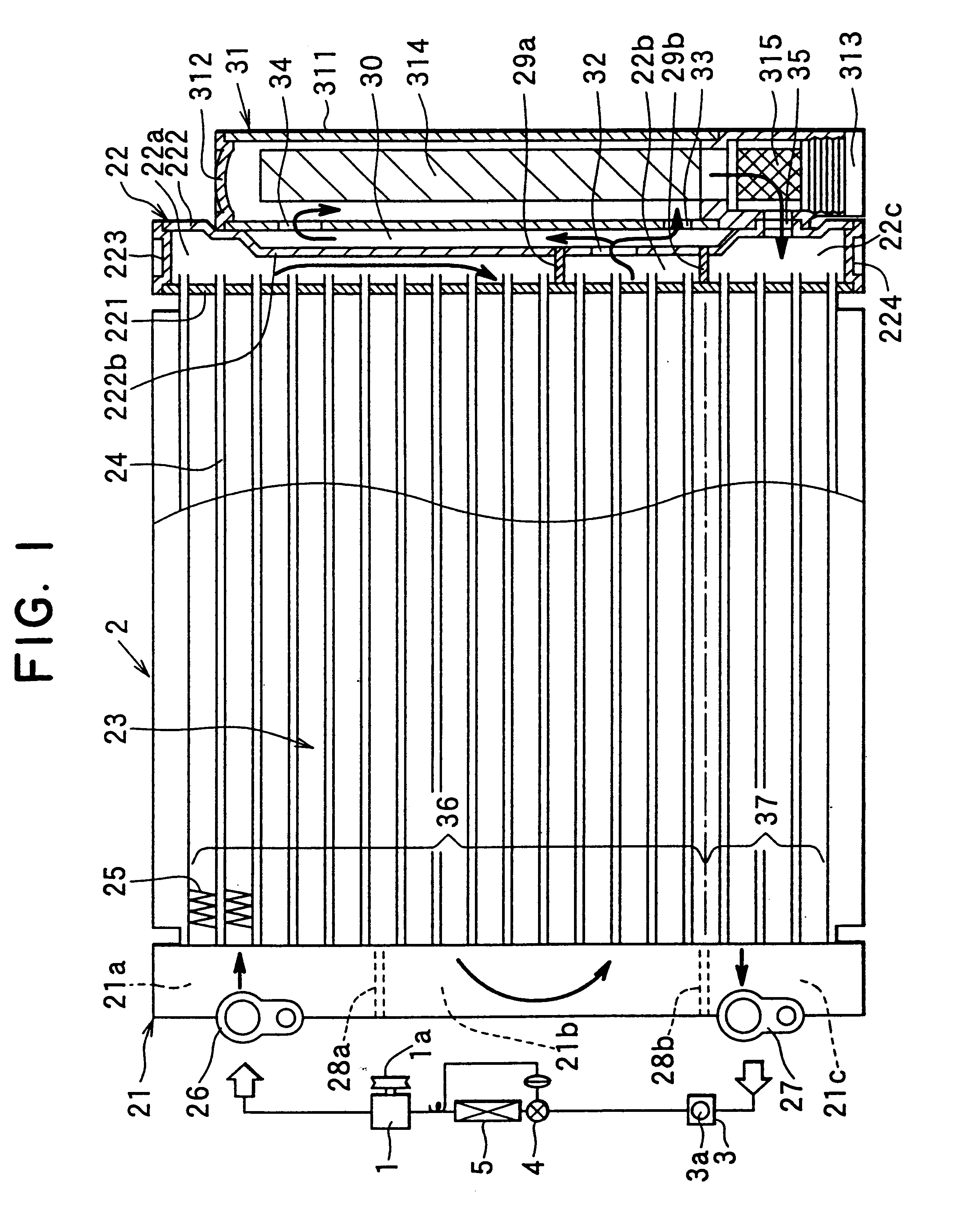
A first preferred embodiment of the present invention will be now described with reference to FIGS. 1-4. In the first embodiment, the present invention is typically applied to a refrigerant cycle of an automotive air conditioner. As shown in FIG. 1, The refrigerant cycle of the automotive air conditioner includes a refrigerant compressor 1, a receiver-integrated refrigerant condenser 2, a sight glass 3, an expansion valve 4, and a refrigerant evaporator 5. All of components of the refrigerant cycle are serially connected by a metal pipe or a rubber pipe to form a closed circuit.

The compressor 1 is connected to an engine disposed within an engine compartment through a belt and an electromagnetic clutch 1a. When the rotation power of the engine is transmitted to the compressor 1 through the electromagnetic clutch 1a, the compressor 1 compresses gas refrigerant sucked therein from the evaporator 5 and then discharges high-pressure high-temperature gas refrigerant to the receiver-integr...

fifth embodiment

In the fifth embodiment, the second separator 28b is disposed in the first header tank 21 at the same height position as the third separator 28c disposed in the second header tank 22. Therefore, the core portion 23 of the condenser 2a is separated into the a condensing portion 36 and a super-cooling portion 37.

The first inlet pipe 46 is connected to the first header tank 21 at a position upper than the first separator 28a to communicate with the upper space 21a. The second inlet pipe 47 is connected to the first header tank 21 at a position lower than the second separator 28b to communicate with the lower space 21c. A first outlet pipe 48 through which refrigerant condensed in the condensing portion 36 of the core portion 23 of the condenser 2a is introduced into the receiver 31a is connected to the first header tank 21 to communicate with a lower side of the intermediate space 21b. Further, a second outlet pipe 49 through which refrigerant from the super-cooling portion 37 of the c...

eighth embodiment

In the eighth embodiment, the three communication holes 51, 52, 53 and tube-insertion holes 54 are opened after the aluminum extrusion. Further, both upper and lower opened ends of the receiving unit 31 and the first header tank 21 are closed by cap members 55, 56.

In the eighth embodiments, both the first header tank 21 and the receiving unit 31 may be integrally bonded by brazing after being separately formed.

In the above-described fifth through eighth embodiments, the super-cooling portion 37 can be independently separately formed from the core portion 23. Even in this case, the present invention can be applied. Further, the super-cooling portion 37 can be omitted, and the refrigerant outlet of the receiver may be directly coupled to the sight glass 3.


PUM


Abstract

In a receiver for separating gas refrigerant and liquid refrigerant and for storing liquid refrigerant for a refrigerant cycle, refrigerant form a condensing portion of a condenser flows into an upper side of a tank member of the receiver from a first refrigerant inlet and flows into a lower side of the tank portion from a second refrigerant inlet. Further, liquid refrigerant stored in the tank member of the receiver is discharged to an outside through a refrigerant outlet. Accordingly, refrigerant from the condensing portion of the condenser flows into the tank portion of the receiver from both upper and lower sides of a gas-liquid boundary surface. As a result, it can prevent the gas-liquid boundary surface of the receiver from being disturbed during a refrigerant introduction of the receiver, while cooling effect of the upper side of the receiver is effectively improved.

Description

1. Field of the InventionThe present invention generally relates to a refrigerant cycle system with an improved refrigerant-sealing performance. More particularly, the present invention relates to a receiver-integrated condenser of a refrigerant cycle, and also relates to a receiver separated from a condenser of a refrigerant cycle, which are suitably applied to an automotive air conditioner.2. Description of Related ArtIn a refrigerant cycle of a conventional air conditioner, a receiver and a condenser are integrally formed so that an installation space of the receiver and the condenser in a vehicle is reduced. For example, U.S. Pat. No. 5,546,761 discloses a receiver-integrated refrigerant condenser as shown in FIG. 13. The receiver-integrated refrigerant condenser includes a pair of first and second header tanks 121, 122, and a core portion 123 disposed between the first and second heater tanks 121, 122. Further, separators are disposed in the first and second header tank 121, 12...

Claims


Application Information

Patent Timeline
IPC IPC(8): F25B39/04F25B40/00F25B43/00F25B40/02
CPCF25B39/04F25B40/02F25B43/003F25B2339/0444F25B2339/0441
Inventor NOBUTA, TETSUJIMATSUO, HIROKIMAKIZONO, KAZUYA
Owner DENSO CORP
Why Eureka
Try Eureka