
To heat exchanger

Inactive Publication Date: 2002-04-30
FEIND JON CHARLES +1
View PDF21 Cites 35 Cited by
  • Summary
  • Abstract
  • Description
  • Claims
  • Application Information

AI Technical Summary

Problems solved by technology

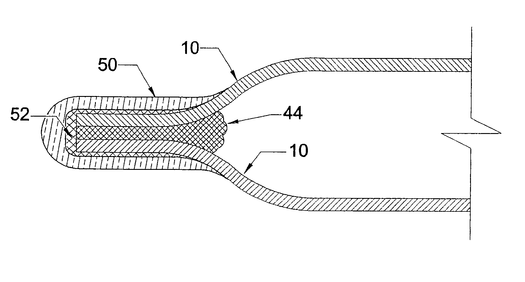
However, the related art uses dimples shown in FIG. 22 and FIG. 19 which are pointed and have small radius curves which cause the dimples to fracture and which cause the dimples to puncture the adjacent layer at the point of contact, in both cases often causing significant leaks.
A layer of sealant is brushed between the touching plate edges, resulting in lack of uniformity and thickness of the sealant, and consequently leaks.
However, the process is unreliable because the flow of sealant cannot be seen, and its uniformity and proper placement cannot be verified.
Thus, leaks are more likely because the related art devices do not use a U-shaped edge clip, their plate edges are not uniformly aligned, are non-parallel, and leak.
Related art exchangers use a snap together alignment detente which is more difficult to form in the plate, takes up more plate area, and is more prone to cracking and leaking.
The related art heat exchangers have a final seal at the corners produced by dipping the corners of the assembly into a vat of sealant or by adding sealant with a glue gun, both less reliable methods which are likely to cause leaks.

Method used


Image

  • To heat exchanger
  • To heat exchanger
  • To heat exchanger

Examples


Embodiment Construction

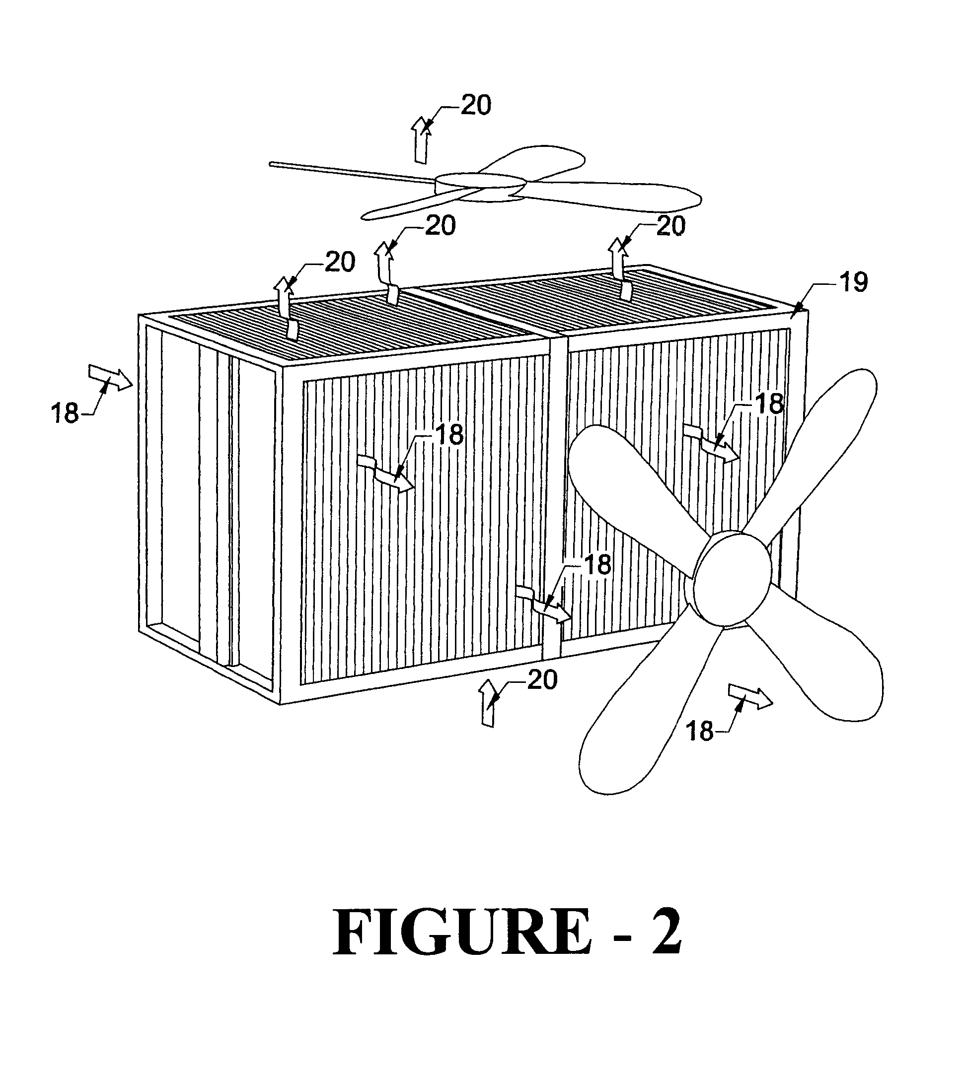
FIG. 18 shows one representative configuration of the present invention. The invention as shown comprises a stack of heat exchanger plates here shown in vertical position. The plate stack assembly is held together by end plates 64, generally L-shaped brackets 60, and reinforcing bands 63. The exchanger will typically have the shape of a cube or rectangular solid, but other shapes are possible.

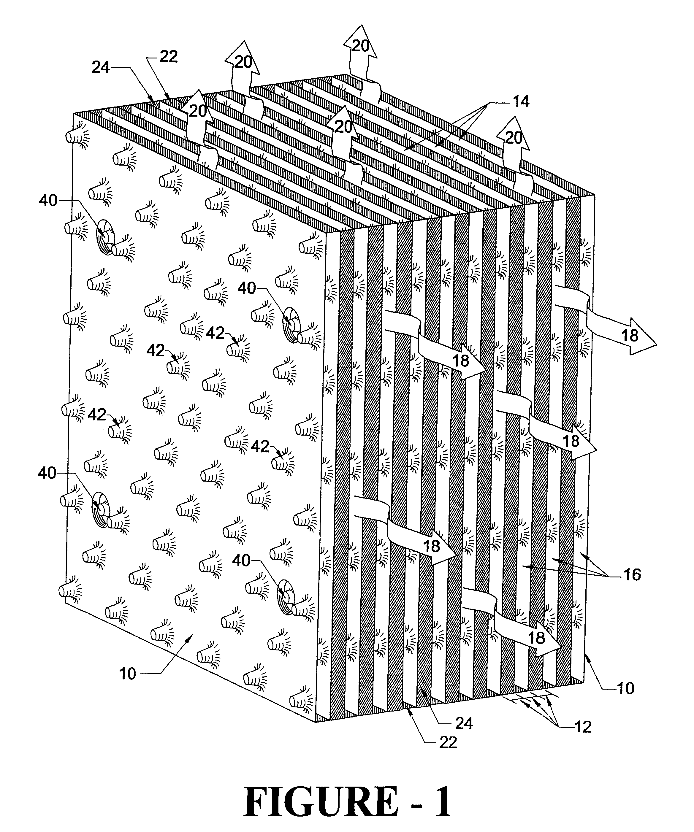
FIG. 2 shows in general form how a primary air flow stream 18 moves horizontally through the heat exchanger, and a secondary air flow stream 20 moves vertically. The air streams are moved through the heat exchanger by fans, or similar method, connected to plenums, one plenum being for the primary air flow stream and the other for the secondary air flow stream. The secondary stream 20 typically comprises outside or process air to be expelled, while the primary air stream 18 is comprised of outside air to be introduced to a space for human comfort. The primary air stream 18 may come from outside ...


PUM

PropertyMeasurementUnit
Structureaaaaaaaaaa
Radiusaaaaaaaaaa
Areaaaaaaaaaaa

Abstract

A structure of, and process for making, an improved heat exchanger. The exchanger may be used for heat transfer between air going to a space for human comfort, and humid, cooled air from an evaporative cooling system. The heat exchanger is made from a series of layers of thermoplastic sheeting spaced apart in a stack by uniquely shaped flat-topped dimples formed therein. The plates are joined together at their edges by adhesive and sealants and aerodynamically designed U-shaped clips. The clips are installed in a manner to form alternating channels of cooled and non-cooled air streams flowing perpendicularly to each other in the stack of plates. Special alignment detentes provide easier stacking and assembly of the plates.

Description

Evaporative coolers or air conditioners are commonly used in dry areas of the world. One drawback of such systems is that even though they reduce the temperature of the air pumped into a space for human comfort, they simultaneously raise the humidity of the air often to the point where the human perception of greater comfort is significantly reduced. It is well known in the air conditioning industry that human beings feel cooler in air which has a lower temperature and humidity than the ambient air. The feeling of greater comfort is partly due to the fact that drier air promotes natural evaporation of moisture through human skin, thereby creating a perception that the air is cooler.The present invention is an improved flat plastic plate heat exchanger involving the evaporative cooling process whereby the cooler but more humid air from the evaporative cooling process is used as a medium to absorb heat from the air being introduced into the space for human comfort without raising the ...

Claims


Application Information

Patent Timeline
IPC IPC(8): B29C65/58B29C65/56F28F3/00F28F21/06F28D9/00F28F3/04F28F21/00F28D5/00B29C65/48B29C65/50F24F1/00F24F1/0067
CPCB29C65/5071B29C66/43B29C65/562B29C65/58B29C66/1122F28D5/00F28D9/0037F28F3/044F28F21/066B29C65/56B29C65/5085B29C66/438B29C66/543B29C65/00B29L2031/18F24F2001/0092F28F2275/025Y02B30/545B29C65/483B29C66/7252B29C66/8322B29C66/71B29C66/112B29C66/131F24F1/0007F24F1/0067B29K2027/06Y02B30/54
Inventor FEIND, JON CHARLESVILLALOBOS, JUAN MANUEL
Owner FEIND JON CHARLES
Learn More