Eureka AIR delivers breakthrough ideas for toughest innovation challenges, trusted by R&D personnel around the world.

Traction mouse pad

a mouse pad and mouse technology, applied in the field of mouse pads, can solve the problems of reducing traction, erratic cursor movement on display monitors, and insufficient room for the typical mouse pad described above, and achieve the effect of improving traction properties

Inactive Publication Date: 2002-05-07
SHIN KWANGSUP
View PDF11 Cites 33 Cited by
  • Summary
  • Abstract
  • Description
  • Claims
  • Application Information

AI Technical Summary

Benefits of technology

to provide such a mouse pad with improved traction properties.
It is a further object of the invention to provide such a mouse pad that is inexpensive to manufacture.
In the preferred embodiment, the top layer is made of a transparent material. Formed over the bottom surface of the top layer is an ink coating that may be seen when the mouse pad is viewed from above. Any graphics, letters, or numbers printed on the ink coating must be applied in reverse order using offset printing techniques. An optional white pigment coating may be applied over the ink coating to improve brilliance. In another embodiment, a bio-ceramic compound that releases beneficial infrared radiation to the user's hand during use may be added to the white pigment coating.
Formed over the ink coating or the white pigment coating is the anti-skid coating. In the preferred embodiment, the anti-skid coating is made of silicone that may be applied as a liquid after being heated using a silk-screen process that substantially reduces manufacturing costs. It should be understood, however, that the anti-skid coating may be made of rubber that bonds to the white pigment layer using standard heat / adhesive bonding techniques.
The resulting mouse pad is extremely thin, light and durable which enables it to be easily carried with a laptop computer and distributed as a promotional item. Because adhesive bonding is not used, the layers of the mouse pad cannot separate and fray like the layers found on a typical mouse pad. Also, the resulting mouse pad may be sold and distributed in a unique roll configuration.

Problems solved by technology

Unfortunately, there isn't sufficient room for the typical mouse pad described above.
One problem with mechanical mice and current mouse pads is that the ball picks up small dirt particles from the top surface of the mouse pad, and deposits them on the rollers.
Over time, these dirt particles reduce traction between the ball and rollers, which results in erratic movement of the cursor on the display monitor.
Mouse pads are normally not used as promotional items because they are too bulky and too expensive to manufacture.

Method used


Image

  • Traction mouse pad
  • Traction mouse pad
  • Traction mouse pad

Examples


Embodiment Construction

)

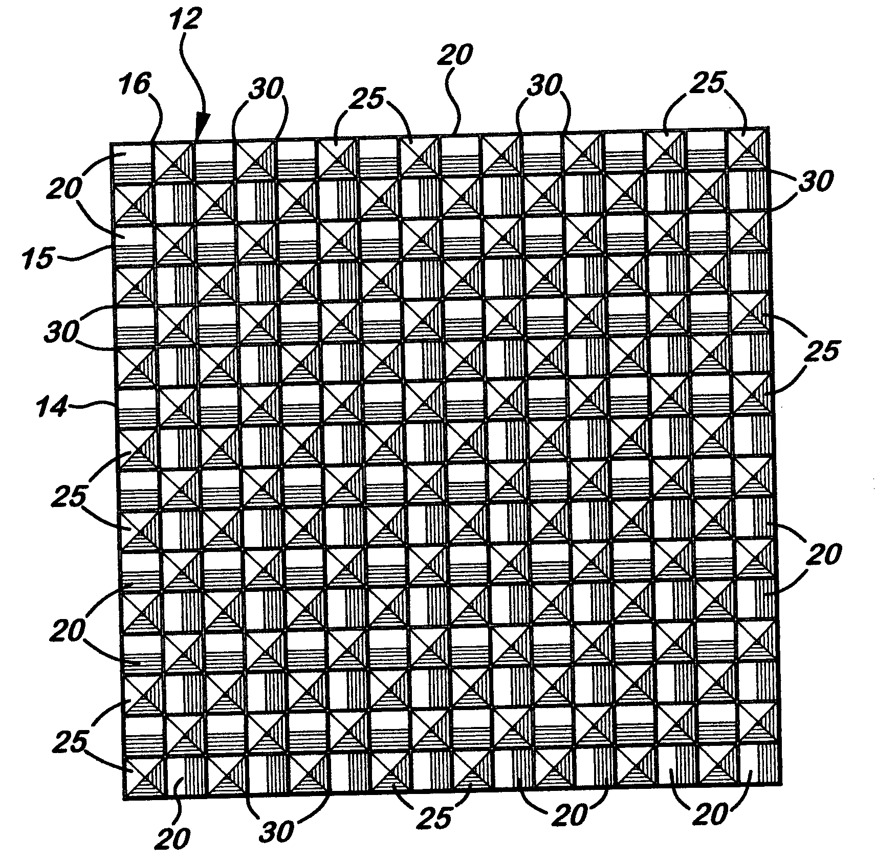
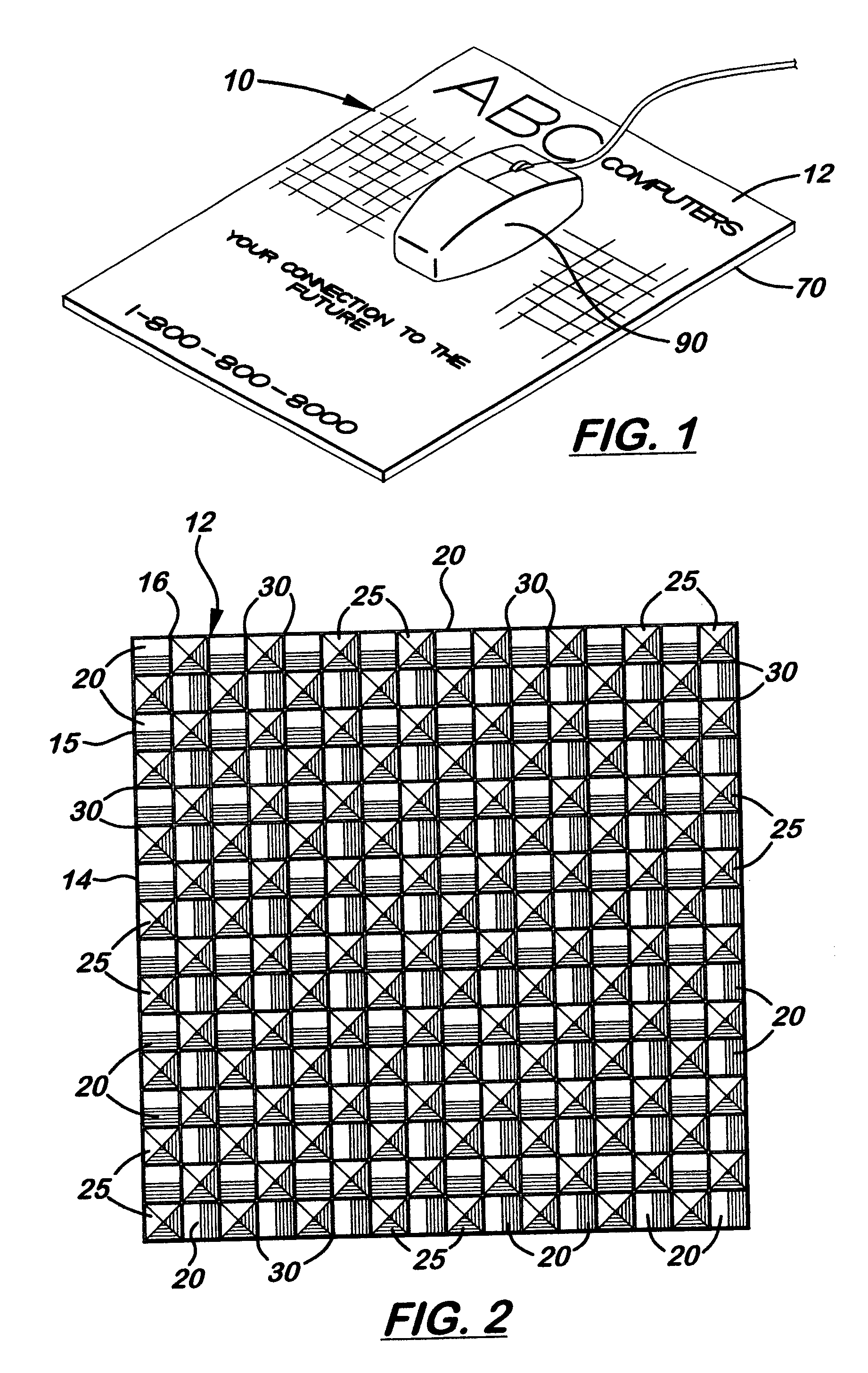
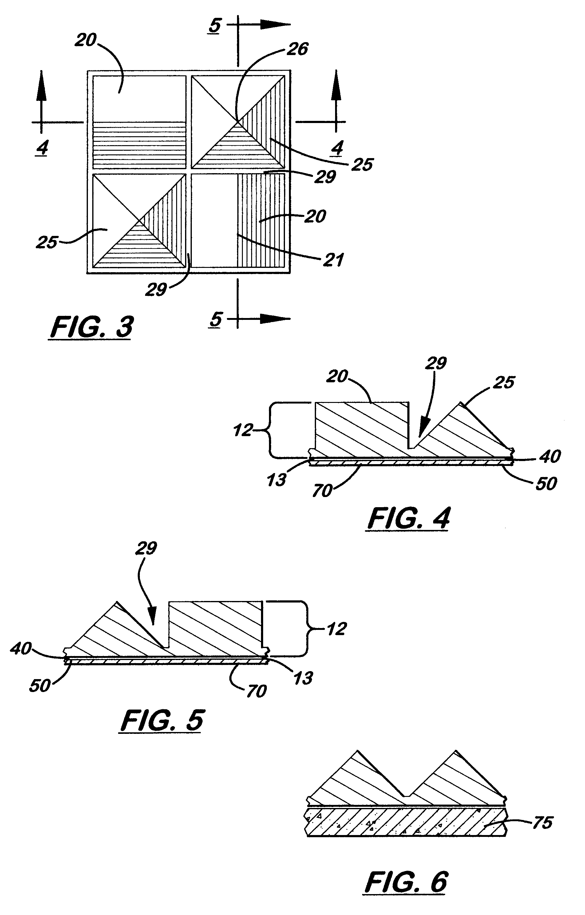
There is shown in the accompanying FIGS. 1-5, a planar mouse pad 10 with self-cleaning and improved traction properties. The mouse pad 10 includes a parallel top layer 12 and a bottom anti-skid layer 70. As shown more clearly in FIG. 2, formed on the top layer 12 is a top control surface 14 with a plurality of alternating micro-size prismatic and pyramidal shapes, 20, 25, respectively. More specifically, the prismatic and pyramidal shapes 20, 25, respectively, extend upward and are integrally formed in the top layer 12. The shapes 20, 25, are alternately arranged in rows 15 and columns 16 perpendicularly to align on the top layer 12. The prismatic shapes 20 measure approximately 0.42 mm in length and 0.42 mm in width and alternate in horizontal and vertical alignment within each row 15 and column 16 so that their respective longitudinal axis 21 intersect the apex 26 of the adjacent pyramidal shapes 25. The base leg of each pyramidal shape 25 measures approximately 0.42 mm in length...


PUM

PropertyMeasurementUnit
heightaaaaaaaaaa
lengthaaaaaaaaaa
thickaaaaaaaaaa

Abstract

A mouse pad with improved self-cleaning and traction features. The mouse pad is a planar structure with a parallel top control layer and a bottom anti-skid coating. Formed on the top layer is a top control layer with a plurality of alternating, equal height, prismatic and pyramidal shapes, which provide improved cleaning and traction properties. Small troughs are formed between the adjacent shapes, which collect fine dirt and dust particles that are swept from the surface of the mouse ball during use. In one embodiment, the top control surface is made of flexible material that allows the prismatic and pyramidal shapes to bend slightly when the ball of a mechanical mouse rolls over the top surface. This bending action provides improved self-cleaning and traction features. In another embodiment, the top layer is made of transparent material. An ink layer may be applied to the bottom surface of the top layer. After the ink coating has dried, a white pigment coating may be applied over the ink coating to enhance the colors. A bio-ceramic compound designed to release infrared radiation may be added to the white pigment coating. Also enclosed herein is a method of manufacturing a mouse pad with a top control layer comprised of alternating prismatic and pyramidal shapes.

Description

1. Field of the InventionThis invention relates to mouse pads, and particularly to mouse pads with improved traction and cleaning features.2. Description of the Related ArtA mechanical mouse is a commonly used pointing device that includes a flat-bottom housing designed to be gripped by one hand, one or more buttons on the top where the user's fingers lie, and a rubber ball that rolls as the housing is moved across a surface. As the ball rolls across the surface, the ball's movement is translated into electrical signals that are transmitted to the computer.Inside the housing, the ball rests against two rollers. These rollers, one for x-axis movement and one for y-axis movement, in turn, rotate additional wheels also located inside the housing. At least one pair of wheels has conductive material on their surfaces that permit an electric current to flow. The electronics in the housing translate these electrical-movement signals into mouse-movement signals that can be used by the compu...

Claims


Application Information

Patent Timeline
Patent Type & Authority Patents(United States)
IPC IPC(8): B32B3/30G06F3/033G06F3/039
CPCB32B3/30G06F3/0395Y10T428/24612Y10T428/23Y10T428/24364Y10T428/24876Y10T428/24736Y10T428/24694Y10T428/24479Y10T428/24562Y10T428/24686Y10T428/162Y10T428/24702Y10T428/22Y10T428/24537Y10T428/24942Y10T428/24868Y10T428/1317Y10T428/24512Y10T428/1314Y10T428/24496Y10T428/232
Inventor SHIN, KWANGSUP
Owner SHIN KWANGSUP
Why Eureka
Eureka Blog
Learn More