Method and apparatus for injecting charge onto the floating gate of a nonvolatile memory cell

a nonvolatile memory cell and floating gate technology, applied in the direction of electrical apparatus, semiconductor devices, transistors, etc., can solve the problems of not being able to scale down to the same degree as the operating voltage of a process under 0.25 .mu.m, and the 5 nm lower bound is not a practical limi

Inactive Publication Date: 2002-05-07
JOHN MILLARD & PAMELA ANN CAYWOOD 1989 REVOCABLE LIVING TRUST AGREEMENT THE
View PDF26 Cites 57 Cited by
  • Summary
  • Abstract
  • Description
  • Claims
  • Application Information

AI Technical Summary

Problems solved by technology

Further, the 5 nm lower bound is not a practical limit because the act of applying the voltage across the oxide to cause tunneling damages the oxide.
Unfortunately, it has been demonstrated that the applied voltages typically employed to inject electrons onto and tunnel off of the floating gate of an EEPROM (electrically erasable programmable read only memory) are not capable of being scaled down to the same degree as the operating voltages of below 0.25 .mu.m processes.

Method used


Image

  • Method and apparatus for injecting charge onto the floating gate of a nonvolatile memory cell
  • Method and apparatus for injecting charge onto the floating gate of a nonvolatile memory cell
  • Method and apparatus for injecting charge onto the floating gate of a nonvolatile memory cell

Examples


Embodiment Construction

Those of ordinary skill in the art will realize that the following description of the present invention is illustrative only and not in any way limiting. Other embodiments of the invention will readily suggest themselves to such skilled persons having the benefit of this disclosure.

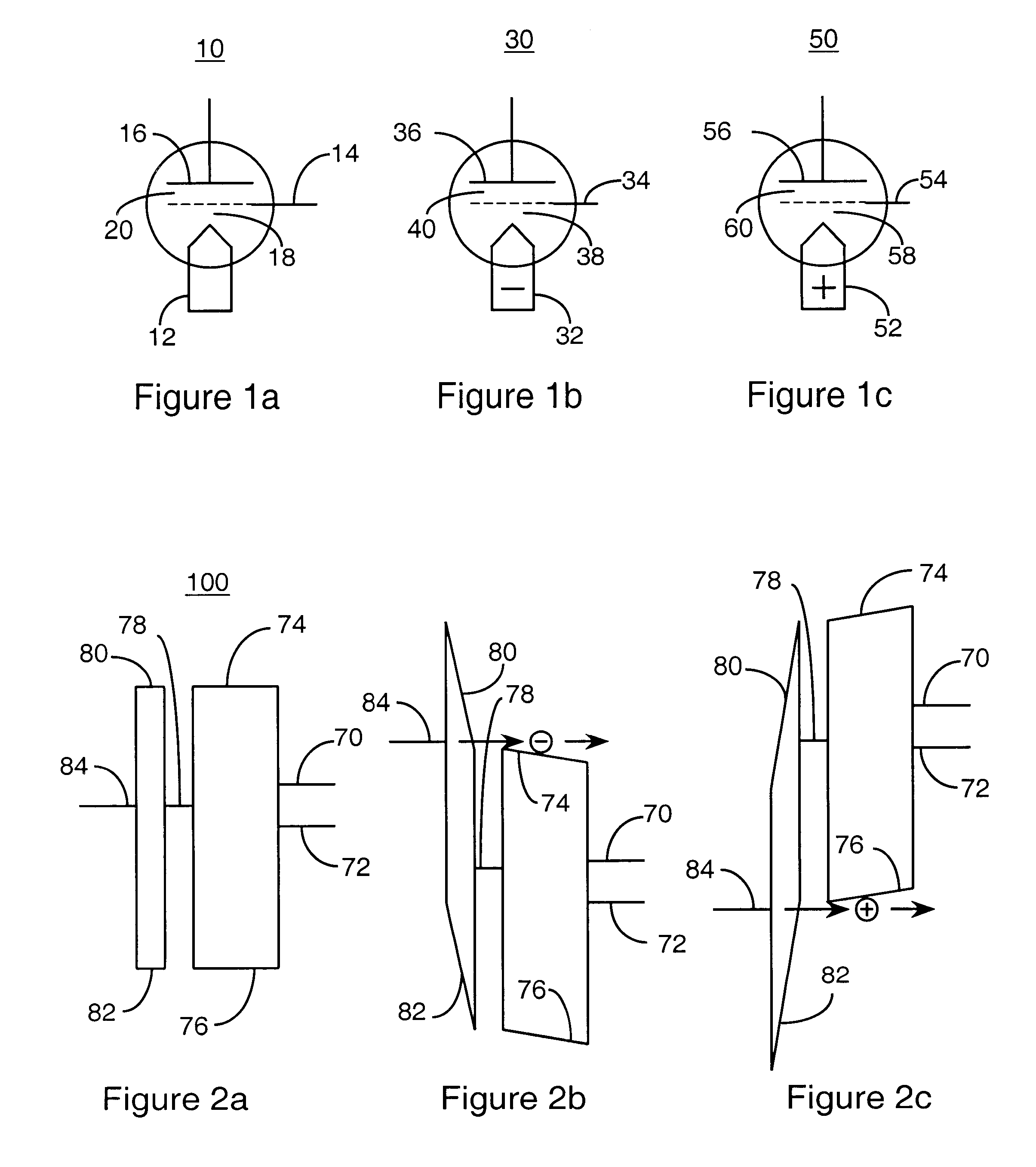
In FIG. 1a, the circuit symbol for a tunneling charge injector 10, according to the present invention, suitable for delivering either electrons or holes to the floating gate of a nonvolatile memory is illustrated. In FIG. 1b, the circuit symbol for a tunneling electron injector 30, according to the present invention, suitable for delivering electrons to the floating gate of a nonvolatile memory is illustrated. In FIG. 1c, the circuit symbol for a tunneling hole injector 50, according to the present invention, suitable for delivering holes to the floating gate of a nonvolatile memory is illustrated. The implementation of the tunneling charge injector 10, tunneling electron injector 30 and tunneling hole in...


PUM


Abstract

A tunneling charge injector includes a conducting injector electrode, a grid insulator disposed adjacent the conducting injector electrode, a grid electrode disposed adjacent said grid insulator, a retention insulator disposed adjacent said grid electrode, and a floating gate electrode disposed adjacent said retention insulator. In the tunneling charge injector, charge is injected from the conducting injector electrode onto the floating gate. Electrons are injected onto the floating gate when the conducting injector electrode is negatively biased with respect to the grid electrode, and holes are injected onto the floating gate when the conducting injector electrode is positively biased with respect to the grid electrode. The tunneling charge injector is employed in a nonvolatile memory cell having a nonvolatile memory element with a floating gate such as a floating gate MOS transistor. In the nonvolatile memory cell, the floating gate of the tunneling charge injector is coupled to or forms a part of the floating gate of the nonvolatile memory element. The tunneling charge injector is employed to inject charge onto the floating gate of the nonvolatile memory element. A memory device includes an array of nonvolatile memory cells wherein each of the memory cells comprises a nonvolatile memory element with a floating gate such as a floating gate MOS transistor and a tunneling charge injector having a floating gate that is either coupled to the floating gate of the nonvolatile memory element or forms a portion of the floating gate of the nonvolatile memory element.

Description

1. Field of the InventionThe present invention relates to nonvolatile memory. More particularly, the present invention relates to methods and apparatus for injecting electrons and holes onto the floating gate of a floating gate MOS transistor nonvolatile memory cell.2. The Prior ArtNonvolatile memories employing floating gate technology have found wide use in a variety of applications, and have become an increasingly important implementation of semiconductor nonvolatile memory. In a floating gate nonvolatile memory, the floating gate electrode of an MOS transistor is electrically isolated from neighboring electrodes by a high quality dielectric that surrounds the floating gate. The state of memory, whether a `0` or a `1`, is determined by the amount of charge on the floating gate.In a memory known to those of ordinary skill in the art as flash memory, electrons are commonly added to the floating gate by a process of hot electron injection that is controlled by the bias applied to va...

Claims


Application Information

Patent Timeline
Patent Type & Authority Patents(United States)
IPC IPC(8): H01L21/70H01L27/115H01L29/66H01L21/8247H01L29/788
CPCH01L27/115H01L29/7883H01L27/11521H10B69/00H10B41/30
Inventor CAYWOOD, JOHN M.
Owner JOHN MILLARD & PAMELA ANN CAYWOOD 1989 REVOCABLE LIVING TRUST AGREEMENT THE
Why Eureka
Try Eureka