Automated target generator range and doppler calculator

a target generator and calculator technology, applied in the field of radar and sonar systems, can solve the problems of presenting a significant burden for software based simulation systems, current radars require very coherent doppler s changes, prior simulators have had difficulty meeting the coherency and speed requirements of current systems

Inactive Publication Date: 2002-05-07
RAYTHEON CO
View PDF4 Cites 31 Cited by
  • Summary
  • Abstract
  • Description
  • Claims
  • Application Information

AI Technical Summary

Problems solved by technology

This problem is multiplied by the fact that each target must be kept track of separately and with considerable accuracy (e.g., plus or minus one foot of error) over a long period of time.
Unfortunately, new radar and sonar modes require the calculations to be performed at the high rate for each target being simulated.
With the multiple target processing capability of current systems, this presents a significant burden for software based simulation systems.
Accordingly, software based systems tend to create simulated target returns which suffer from noncoherent jumps in both the time and frequency domains.
Unfortunately, current radars require very coherent Doppler s changes in the simulated targets to perform synthetic aperture radar (SAR) type processing.
As a result, prior simulators have had difficulty meeting the coherency and speed requirements of current systems.
Hence, one of the disadvantages of the prior approach lies in the complex and intolerant circuit design required by conventional teachings.
In addition, conventional radar target simulation circuits had large bus and bandwidth requirements, zero tolerance for error, and no practical recovery mechanism short of reset.
This process tends to drop coherent RF pulse outputs.
In short, target simulation circuits designed in accordance with conventional teachings typically required a large number of discrete logic circuit elements, were considerably complex, offered no other usable features and presented numerous service and maintainability issues.

Method used


Image

  • Automated target generator range and doppler calculator
  • Automated target generator range and doppler calculator
  • Automated target generator range and doppler calculator

Examples


Embodiment Construction

Illustrative embodiments and exemplary applications will now be described with reference to the accompanying drawings to disclose the advantageous teachings of the present invention.

While the present invention is described herein with reference to illustrative embodiments for particular applications, it should be understood that the invention is not limited thereto. Those having ordinary skill in the art and access to the teachings provided herein will recognize additional modifications, applications, and embodiments within the scope thereof and additional fields in which the present invention would be of significant utility.

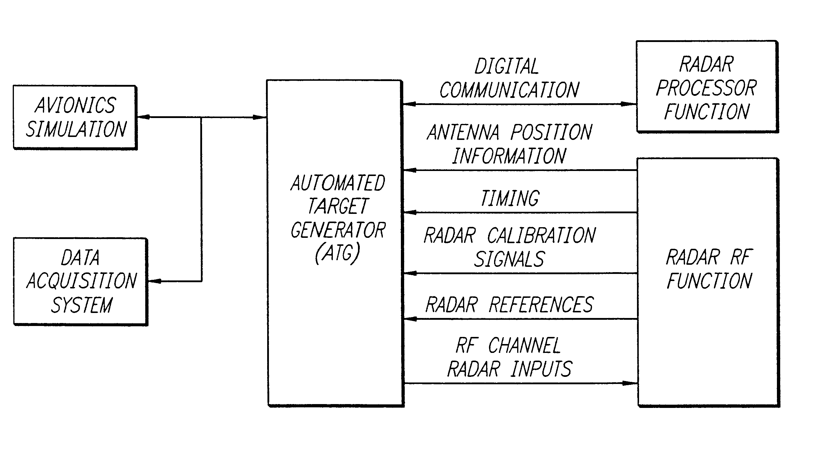
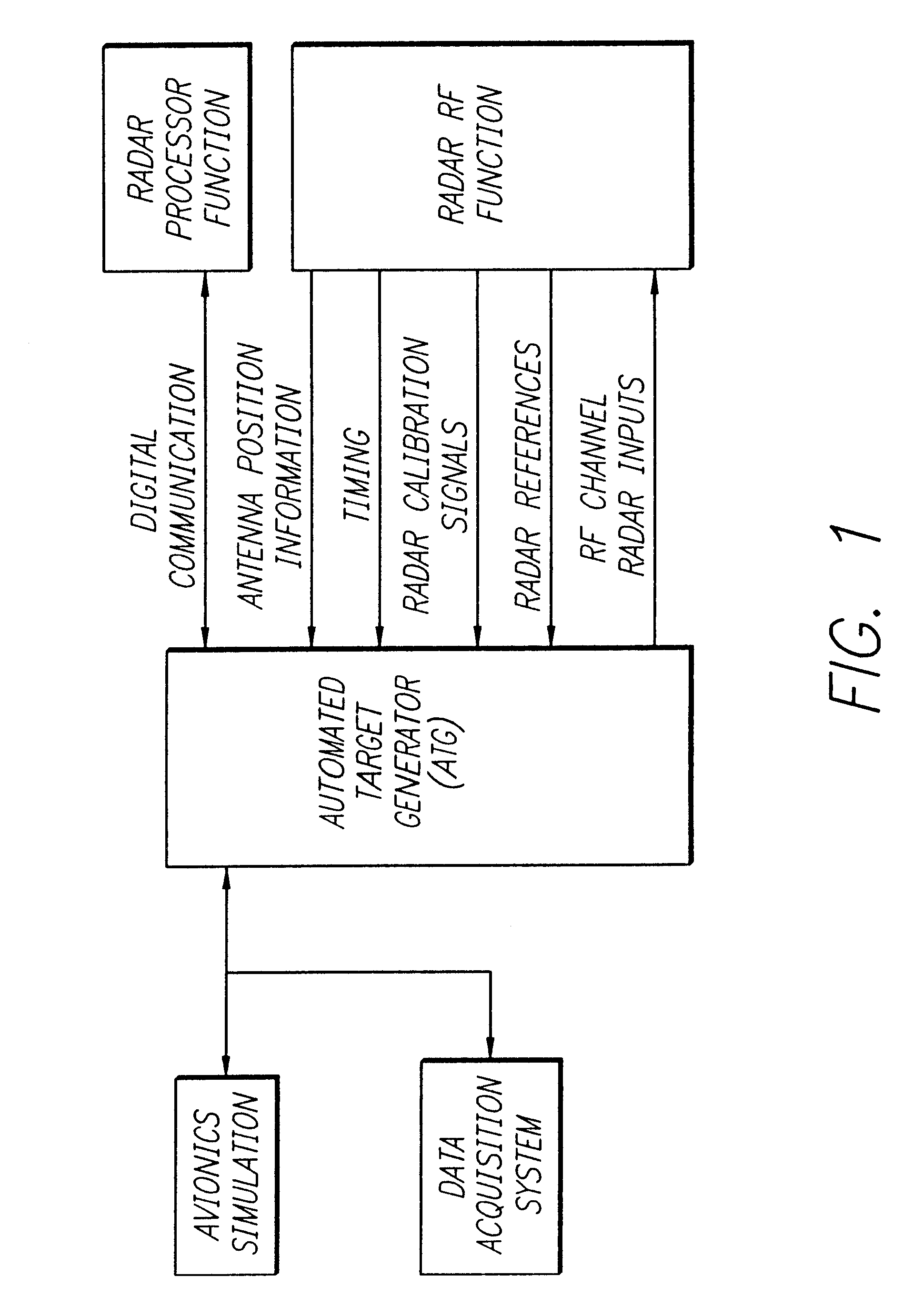
FIG. 1 is a block diagram showing an illustrative application of the automated target simulation system of the present invention. The arrangement 1 includes an automated target generator 10 constructed in accordance with the teachings of the present invention. The target generator 10 communicates with the processor function 16 of a radar system under test. The t...


PUM


Abstract

An automated simulator for radar and sonar applications. The inventive simulator is implemented in hardware and generates current parameters with respect to a simulated target in response to a plurality of initial values with respect thereto. In the illustrative embodiment, the initial values include range, velocity, and acceleration and are stored in first, second and third register respectively. In the best mode, the invention is implemented in a field-programmable gate array. The inventive target simulator also includes a range delay circuit for generating a simulated return from the simulated target. The range delay circuit includes logic for determining whether a simulated pulse train to be received is ambiguous or unambiguous and adjusting the pulse repetition rate of the pulse train accordingly. The range delay circuit calculates die initial time that a packet needs to make the trip to and from the target. Then, in the ambiguous case, the circuit only calculates how long it takes between pulses to arrive rather than the entire round trip. When the round trip distance and the ambiguous time are identical, the range delay circuit calculates both ambiguous and unambiguous signals and signals the return of whichever type arrives first. After the initial rate is calculated then the shortest calculation between the ambiguous and unambiguous pulses determine the timing for the next returned pulse.

Description

1. Field of the InventionThe present invention relates to radar and sonar systems. More specifically, the present invention relates to systems and methods for simulating targets for testing radar and sonar systems.2. Description of the Related ArtIn the radar and sonar fields, target returns arc simulated to test hardware and software associated with the system. Three essential vectors must be generated in order to simulate a target: range, velocity, and acceleration. These three vectors must be stored and recalculated at a very high rate (e.g., every 4 microseconds) in order to meet today's radar and sonar requirements. This problem is multiplied by the fact that each target must be kept track of separately and with considerable accuracy (e.g., plus or minus one foot of error) over a long period of time. Previously, these calculations were performed in software.Unfortunately, new radar and sonar modes require the calculations to be performed at the high rate for each target being s...

Claims


Application Information

Patent Timeline
Patent Type & Authority Patents(United States)
IPC IPC(8): G01S7/40
CPCG01S7/4052G01S2007/4082G01S7/4082
Inventor MONTAGUE, WARREN J.BIRCSAK, GARIN S.KEIGHARN, JOHN K.BARBOZA, JORGE L.ERWIN, ROBERT W.
Owner RAYTHEON CO
Why Eureka
Try Eureka