

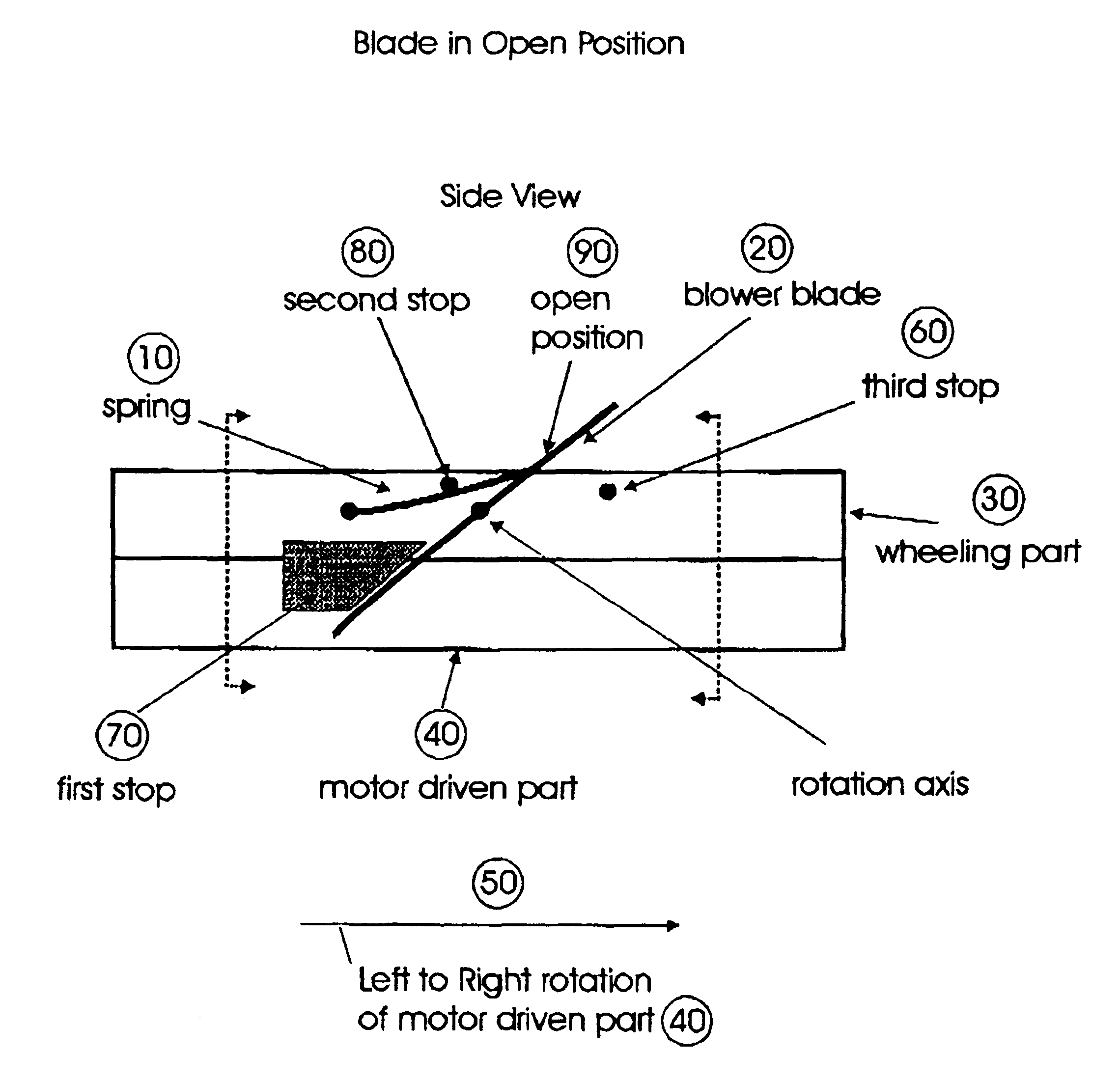
Fan with self closing blades
- Summary
- Abstract
- Description
- Claims
- Application Information
AI Technical Summary
Benefits of technology
Problems solved by technology
Method used
Image

Examples
Embodiment Construction
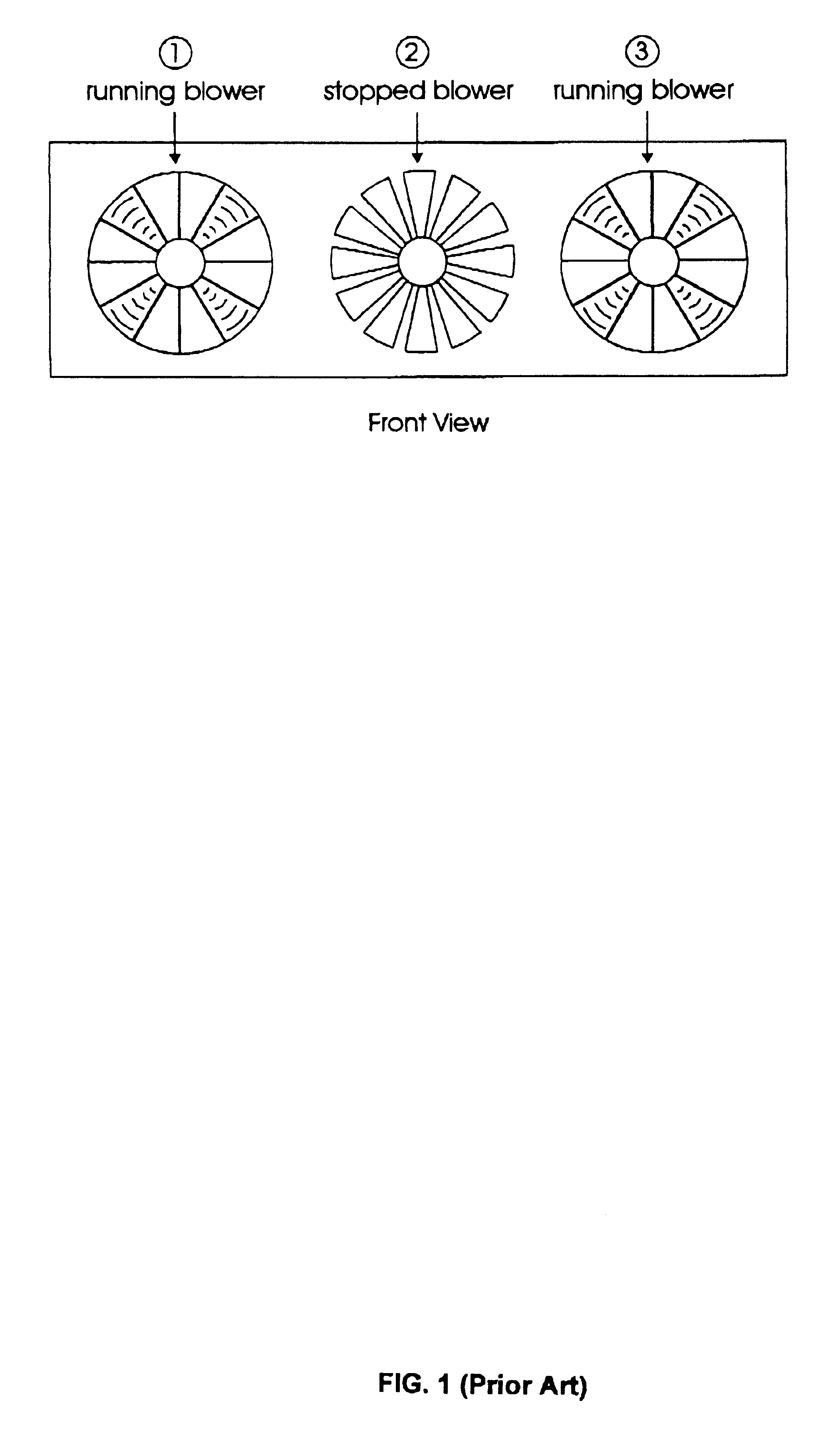
An object of the invention is to avoid the problem of air leakage generated by a failing or malfunctioning fan. When a fan fails, it not only stops producing an air flow, but it also generates an air leakage to the box. Consequently, additional blowing capacity is required from the fan system to compensate for this air leakage and to correctly cool electronic devices arranged within the box. This problem is illustrated in FIGS. 1 and 2.
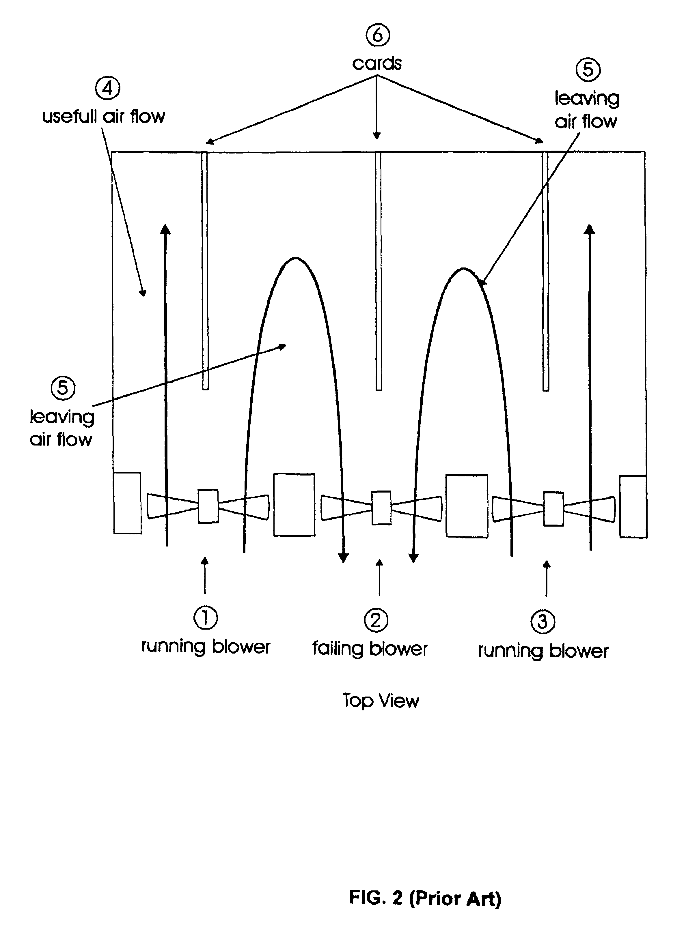
FIG. 1 is a front view of a fan system according to the prior art for cooling a box or an enclosure comprising a plurality of electronic devices. FIG. 2 is a top view of a box or an enclosure comprising a plurality of electronic cards (6) and a plurality of fans (1,2,3) for cooling the electronic components mounted on said cards (6) according to prior art. The fan (2) in the middle of the cooling system is stopped. The two other fans on the left (1) and on the right (3) are operating (blowing).
One part of the remaining air flow (4) is oriented towards...
PUM
 Abstract
Description
Claims
Application Information