

System and method for notifying a user of voice mail messages at a cell phone site
a cell phone site and voice mail technology, applied in the field of voice mail messaging, can solve the problem of no system providing a message waiting indicator
- Summary
- Abstract
- Description
- Claims
- Application Information
AI Technical Summary
Problems solved by technology
Method used
Image

Examples
first embodiment
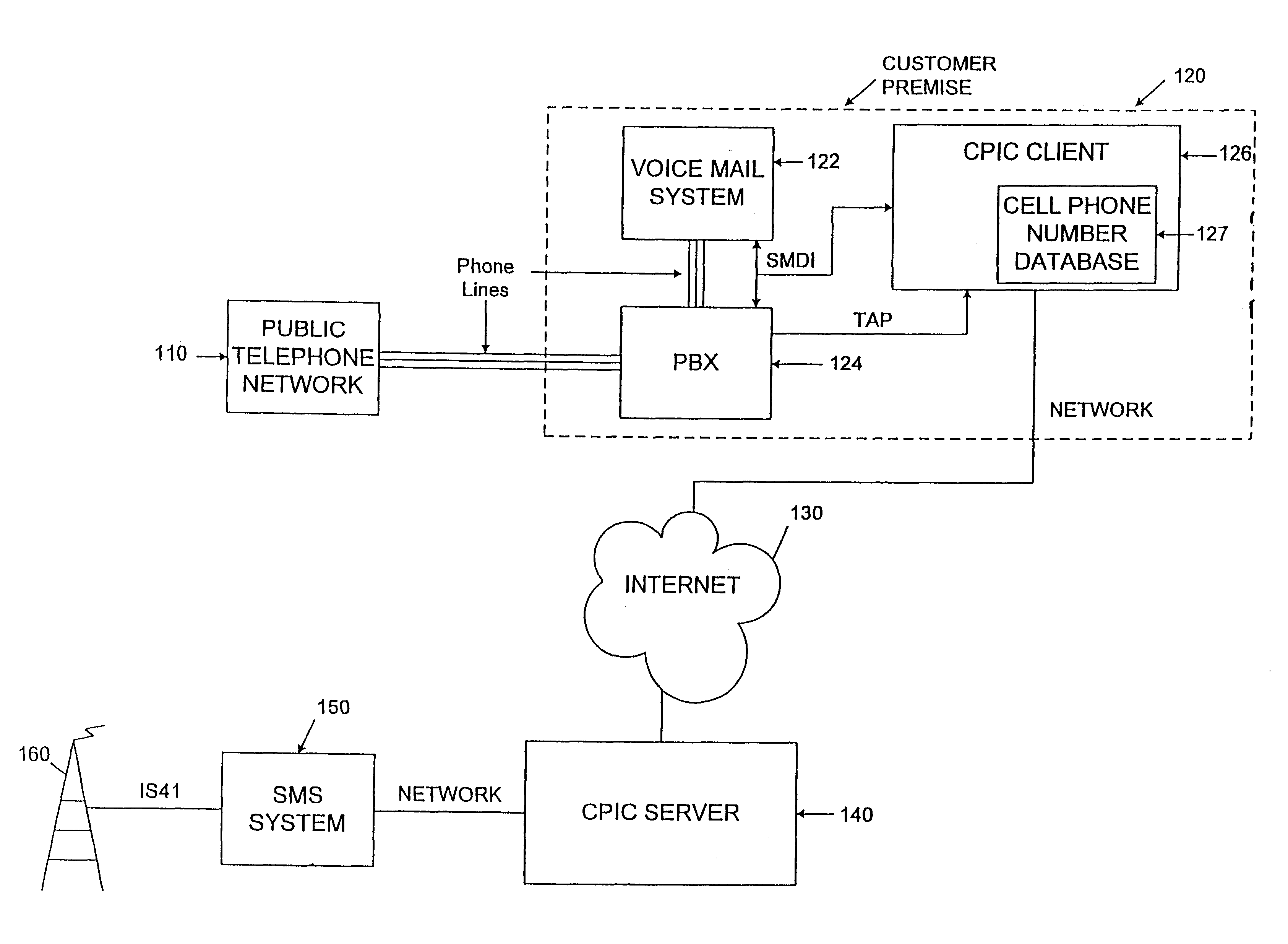
FIG. 1A is a block diagram showing a communications configuration according to the present invention. FIGS. 2 and 3 are flow charts that show the steps for sending a MWI on and off signal to a cell phone.
Referring to FIG. 1A, public telephone network 110 forwards incoming telephone calls directed to private branch exchange (PBX) 124 at a customer premise 120. PBX 124 directs the calls to extensions within the customer premise 120. PBX 124 decides where to route incoming calls based on the number dialed. PBX 124 also handles redirection of calls to different internal numbers, including the voice mail system 122. If, for instance, a phone is not answered after a predetermined number of rings, PBX 124 reroutes the call to the voice mail system 122. Also, if an extension is forwarded to another number, PBX 124 automatically forwards the call to the forwarded number.
Each time a voice mail message is left on the voice mail system 122, the voice mail system 122 generates an industry standa...
second embodiment
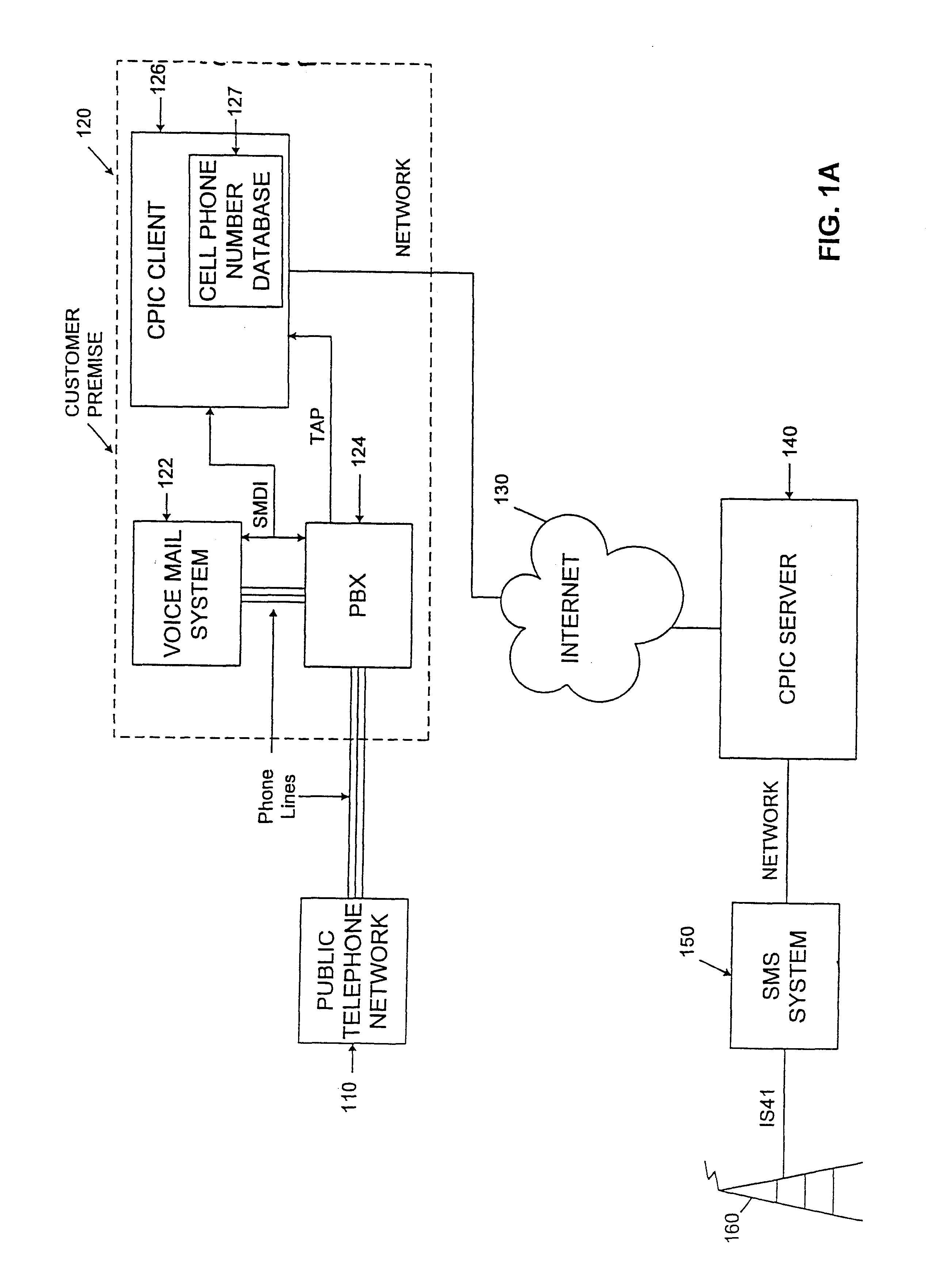
FIG. 1B shows the present invention according to another embodiment of the present invention. The communication system in FIG. 1B includes many of the same elements as in FIG. 1A. A significant difference is that voice mail system 122 does not forward any TAP information to CPIC client 126 and CPIC client 126 has access to a cell phone number database 127 that includes a list of voice mail numbers, their corresponding cell phone numbers and the user's desired notification format. If a user changes an associated cell phone number, the voice mail administrator must update the database. FIGS. 4 and 5 are flow charts of the steps for sending a MWI on or off signal to a cell phone according to the present invention shown in FIG. 1B.
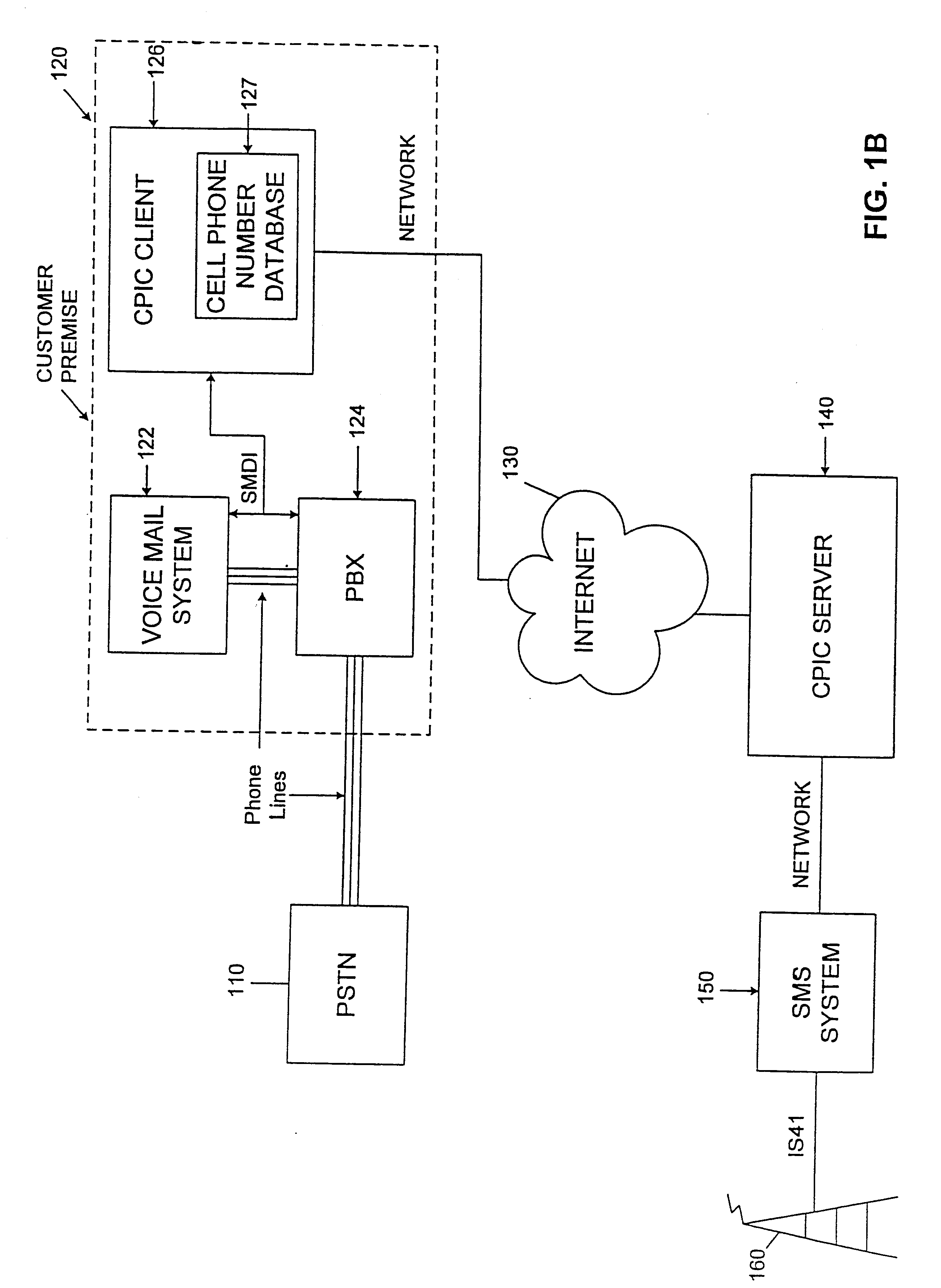
FIG. 1C is a block diagram showing the communication system according to a third embodiment of the present invention. This embodiment includes many of the same elements as FIG. 1A; however, the voice mail system does not send TAP information to the PBX 124 and...
third embodiment
FIG. 1C shows the present invention that includes many of the elements of FIG. 1A except that a TAP protocol is not used. Alternatively, this embodiment uses an in-band signaling protocol.
FIG. 6 shows the steps corresponding to this embodiment. A voice mail message is deposited in a voice mail box at voice mail system 122 (step 610). Voice mail system 122 generates a message waiting indicator signal, MWI-on, using the SMDI protocol and forwards this signal along with the voice mail number to CPIC client 126 and optionally to PBX 124 (step 620). CPIC client 126 awaits a DTMF data stream that includes the voice mail number, a cell phone number, a number of messages, and desired notification format (step 630). CPIC client 126 determines whether the DTMF stream has been received within a given time period, such as two minutes (step 640). If CPIC client 126 receives the DTMF stream, the cell phone number, number of messages, a MWI-on signal and desired notification format are sent by CPI...
PUM
 Abstract
Description
Claims
Application Information