Supercharge Your Innovation With Domain-Expert AI Agents!

Phase-locked loop circuit with high lock speed and stability

a phase-locked loop and high lock speed technology, applied in the direction of generator stabilization, pulse automatic control, electrical equipment, etc., can solve the problem of inability to improve lock speed and stability at the same tim

Inactive Publication Date: 2002-05-21
MITSUBISHI ELECTRIC CORP +1
View PDF2 Cites 8 Cited by
  • Summary
  • Abstract
  • Description
  • Claims
  • Application Information

AI Technical Summary

Problems solved by technology

With the foregoing configuration, the conventional phase-locked loop circuit has a tradeoff between the lock speed and stability concerning the amount of change in the potential of the voltage signal passing through the lowpass filter 3, offering a problem of unable to improved the lock speed and stability at the same time.

Method used


Image

  • Phase-locked loop circuit with high lock speed and stability
  • Phase-locked loop circuit with high lock speed and stability
  • Phase-locked loop circuit with high lock speed and stability

Examples


embodiment 1

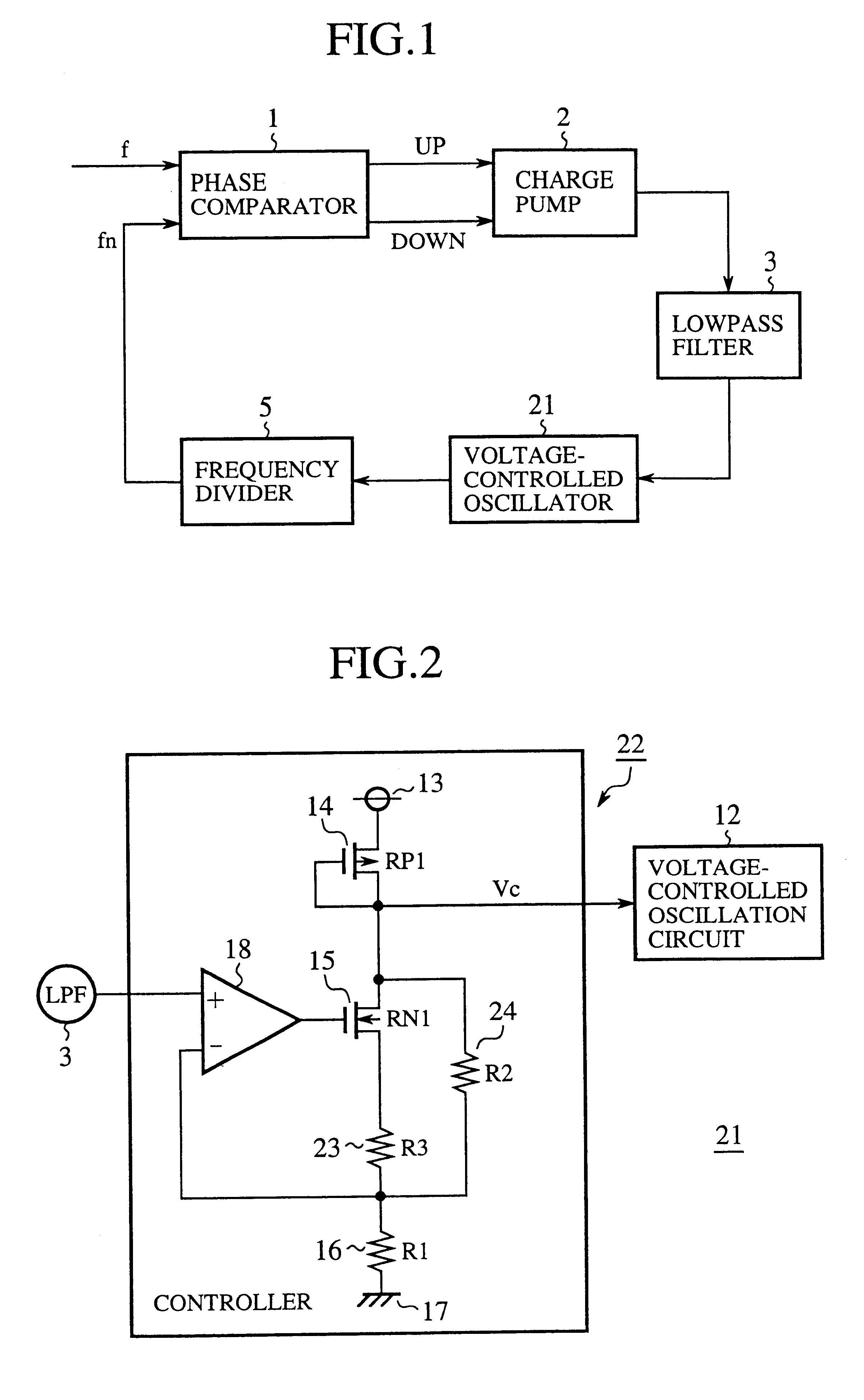
FIG. 1 is a block diagram showing a configuration of the phase-locked loop circuit in accordance with the present invention. In this figure, the reference numeral 1 designates a phase comparator for outputting an error signal corresponding to a phase difference between a reference signal f and an output signal fn; 2 designates a charge pump for outputting a voltage signal corresponding to the error signal; 3 designates a lowpass filter for passing a low frequency component of the voltage signal; 21 designates a voltage-controlled oscillator for outputting an oscillation frequency corresponding to the voltage signal passing through the lowpass filter 3; and 5 designates a frequency divider for supplying the phase comparator 1 with the output signal fn obtained by dividing the oscillation frequency fed from the voltage-controlled oscillator 21.

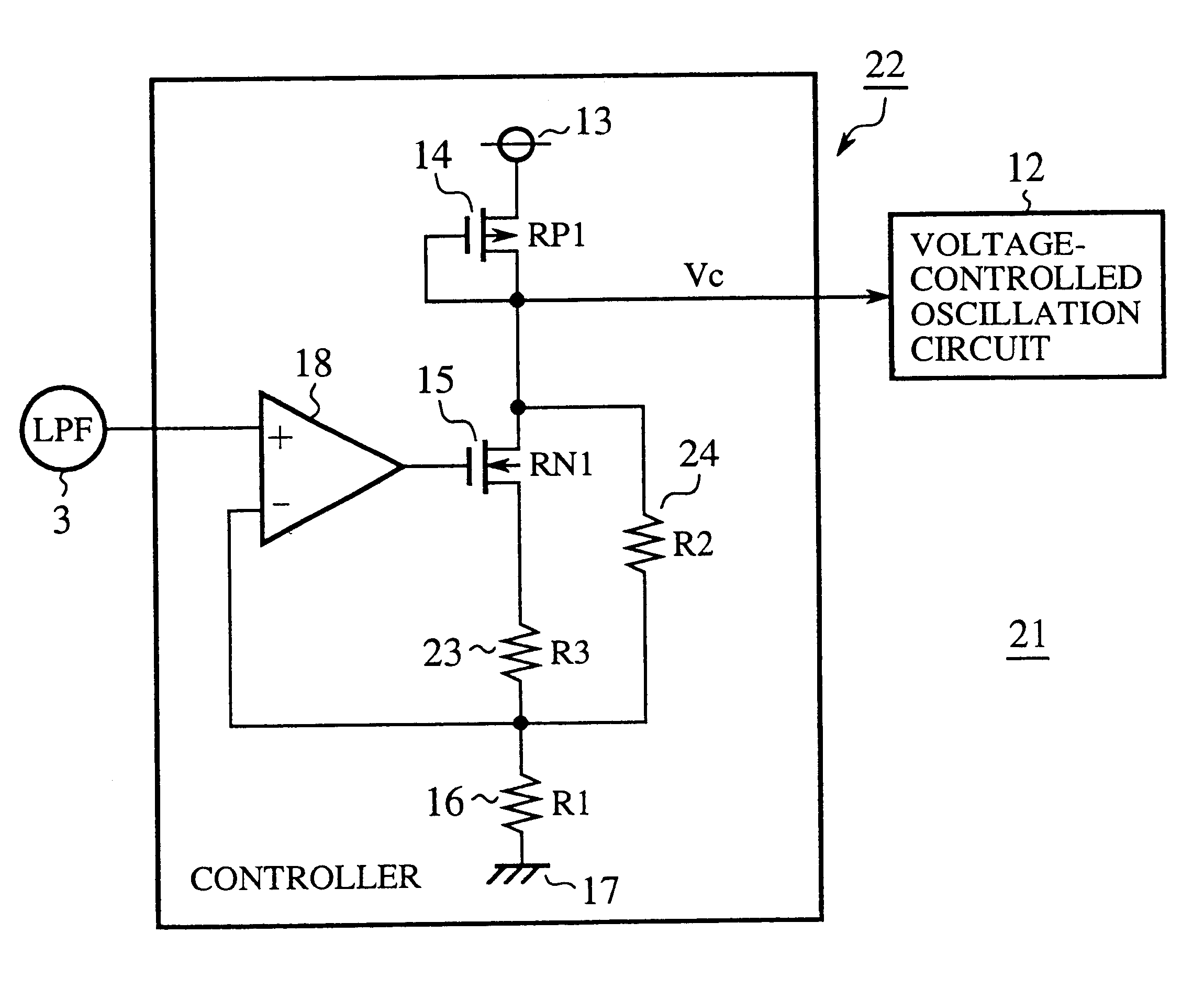
FIG. 2 is a circuit diagram showing a configuration of the voltage-controlled oscillator 21 of the present embodiment 1. In this figure, the re...

embodiment 2

FIG. 5 is a circuit diagram showing an embodiment 2 of the voltage-controlled oscillator in accordance with the present invention. In this figure, reference numerals 23a and 23b designate resistors connected in parallel, the resistances of which are R3 and R3', respectively; 24a and 24b designate resistors connected in parallel, the resistances of which are R2 and R2', respectively; and 25a, 25b, 26a and 26b designate switches connected in series with the resistors 23a, 23b, 24a and 24b to select any of the resistors 23a, 23b, 24a and 24b. The remaining configuration is the same as that of FIG. 2.

Next, the operation of the present embodiment 2 will be described.

In FIG. 5, when the switches 25a and 25b are turned on while the switches 25b and 26b are kept off by software control, the control voltage Vc for controlling the voltage-controlled oscillation circuit 12 is determined by the divided voltage produced by dividing the voltage across the DC power supply 13 to the ground 17 by re...


PUM


Abstract

A phase-locked loop circuit includes a voltage-controlled oscillator that includes a series circuit having a P-channel transistor, N-channel transistor, a third resistor and a first resistor connected in series in this order; a second resistor connected in parallel with a series circuit of the N-channel transistor and the third resistor; and an operational amplifier having its non-inverting input terminal connected to an output terminal of a lowpass filter, its inverting input terminal connected to a connected point of the third resistor and first resistor, and its output terminal connected to a gate of the N-channel transistor. The variable region of the resistance of the parallel circuit consisting of the N-channel transistor and the third and first resistors can be limited, which in turn enables the variable region of the control voltage of the voltage-controlled oscillator including a locking control voltage to be limited to a desired range. This makes it possible to limit the oscillation frequency of the voltage-controlled oscillator determined by the voltage signal fed from the lowpass filter to a desired range, and to increase its lock speed and stability at the same time.

Description

1. Field of the InventionThe present invention relates to a phase-locked loop circuit.2. Description of Related ArtFIG. 7 is a block diagram showing a conventional phase-locked loop circuit. In this figure, the reference numeral 1 designates a phase comparator for outputting an error signal corresponding to a phase difference between a reference signal f and an output signal fn; 2 designates a charge pump for outputting a-voltage signal corresponding to the error signal; 3 designates a lowpass filter for passing a low frequency component of the voltage signal; 4 designates a voltage-controlled oscillator for outputting an oscillation frequency corresponding to the voltage signal passing through the lowpass filter 3; and 5 designates a frequency divider for supplying the phase comparator 1 with the output signal fn obtained by dividing the oscillation frequency fed from the voltage-controlled oscillatorFIG. 8 is a circuit diagram showing a configuration of the conventional voltage-co...

Claims


Application Information

Patent Timeline
Patent Type & Authority Patents(United States)
IPC IPC(8): H03L7/08H03L7/099H03L7/089H03L7/093H03L7/16H03L7/18H03L7/107
CPCH03L7/0891H03L7/099H03L7/093H03L7/18
Inventor TAKIKAWA, YUTAKA
Owner MITSUBISHI ELECTRIC CORP
Features
  • R&D
  • Intellectual Property
  • Life Sciences
  • Materials
  • Tech Scout
  • Unparalleled Data Quality
  • Higher Quality Content
  • 60% Fewer Hallucinations
Learn More