Radio telephone system within a vehicle with enhanced safety features

a radio telephone system and vehicle technology, applied in the field of radio telephone systems within vehicles, can solve the problems of traffic accidents, reduced portability of mobile telephone terminals,

Inactive Publication Date: 2002-05-21
NEC CORP
View PDF15 Cites 57 Cited by
  • Summary
  • Abstract
  • Description
  • Claims
  • Application Information

AI Technical Summary

Problems solved by technology

Therefore, the convenience of portability in a mobile telephone terminal is extremely reduced.
Further, the use of mobile telephone while driving a car frequently causes a traffic accident.

Method used


Image

  • Radio telephone system within a vehicle with enhanced safety features
  • Radio telephone system within a vehicle with enhanced safety features
  • Radio telephone system within a vehicle with enhanced safety features

Examples


first embodiment

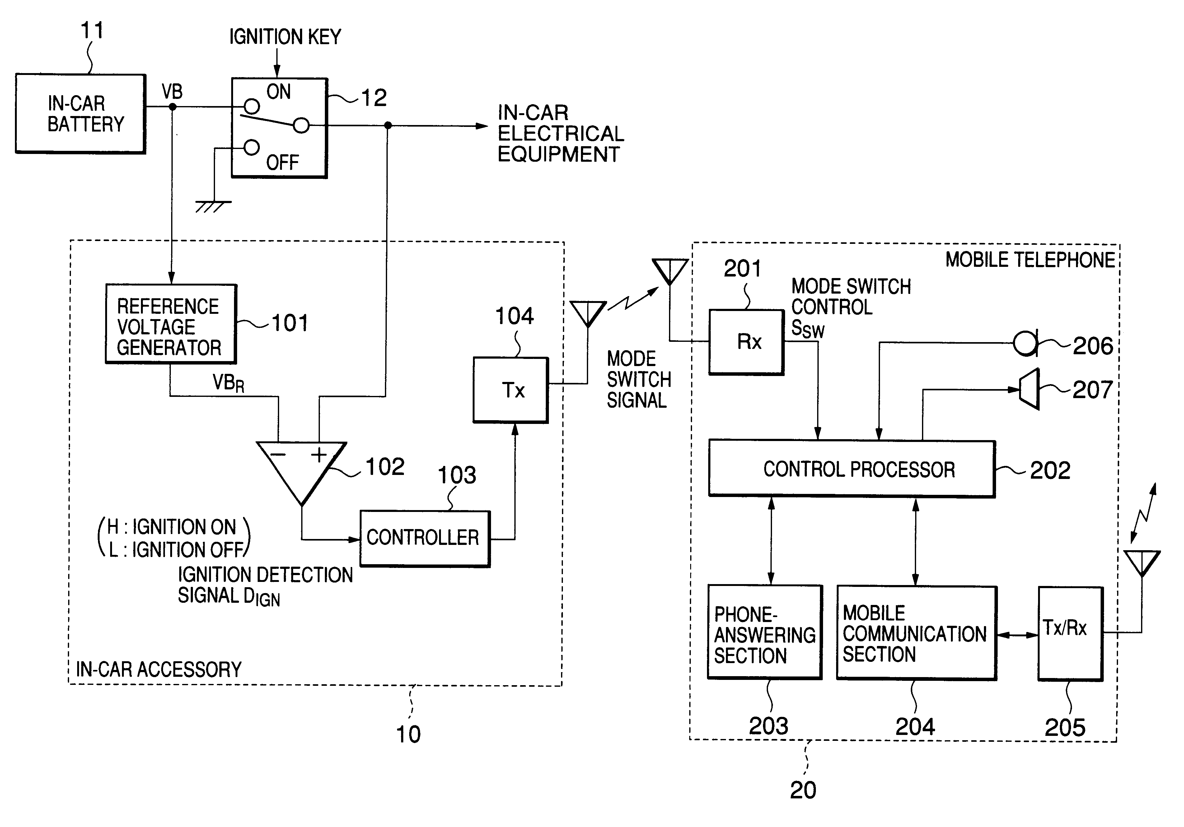
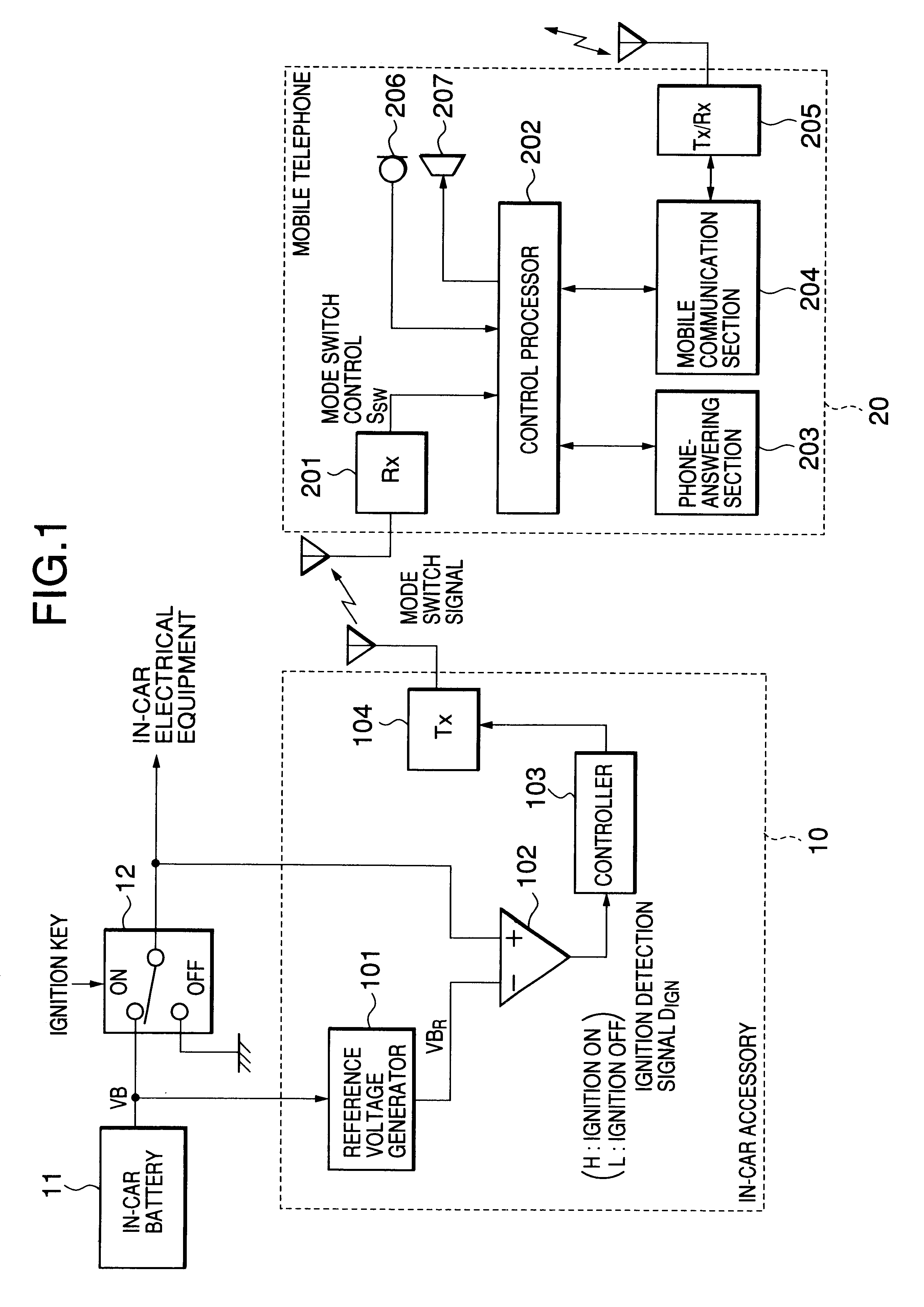
As described above, by the driver switching the ignition key on / off, the mobile telephone 20 is automatically set to phone-answering / communication mode. Therefore, the driver does not have to handle the mobile telephone 20 while driving, resulting in the reduced possibility of traffic accident occurrence. Since the mobile telephone 20 is not connected to the in-car accessory 10 by a cable or the like, the driver can take the mobile telephone 20 out of the car.

second embodiment

Referring to FIG. 3, there is shown an in-car accessory 30 which transmits the mode switch signal to the mobile telephone 20 based on the speed of the car.

The in-car accessory 30 includes a car speed detector composed of a converter 301, a reference voltage generator 302 and a comparator 303. The converter 301 receives car speed data from in-car equipment and produces a speed reflecting voltage VS varying according to the speed. The reference voltage generator 302 generates a predetermined reference voltage VS.sub.R from the battery voltage VB. The comparator 303 compares the speed reflecting voltage VS to the reference voltage VS.sub.R. The comparator 303 produces a speed detection signal D.sub.S which changes in voltage depending on whether the speed reflecting voltage VS is lower than the reference voltage VS.sub.R. More specifically, the speed detection signal D.sub.S changes to a high-voltage level when the speed reflecting voltage VS is equal to or greater than the reference v...

third embodiment

Referring to FIG. 4, infrared transmitting and receiving means 401 and 402 may be used in place of the radio transmitter 104 and receiver 201 of FIG. 1. In the third embodiment, the in-car accessory 10 is provided with an infrared transceiver 401 and the mobile telephone 20 is provided with an infrared transceiver 401. The other circuit blocks similar to those previously described with reference to FIG. 1 are denoted by the same reference numerals and the descriptions are omitted. However, control operations of the controller 103 and the control processor 202 are different from those of FIGS. 2A and 2B. The control operations according to the third embodiment will be described hereinafter.

Referring to FIG. 5A, the controller 103 monitors the detection signal D.sub.IGN received from the voltage comparator 102 at all times (step S501). When the detection signal D.sub.IGN changes to a high-voltage level or a low-voltage level (YES in step S501), the controller 103 controls the infrared...


PUM


Abstract

A radio telephone system for use in a vehicle is composed of an accessory mounted in the vehicle and a radio telephone that is separated from the accessory. The accessory transmits a mode switch signal indicating an operation state of the vehicle to the radio telephone by wireless means such as radio or infrared. When receiving the mode switch signal from the accessory, the radio telephone changes its operation mode depending on the mode switch signal. The operation state of the vehicle is an on/off state of an ignition key or a speed of the vehicle.

Description

1. Field of the InventionThe present invention generally relates to a radio telephone system within a vehicle, and in particular to a radio telephone system that can change the operation mode of a radio telephone terminal.2. Description of the Related ArtA car-mounted telephone system having a function of switching its operation mode between a driving mode and a stop mode has been disclosed in Japanese Patent Unexamined Publication No. 4-192949. This conventional telephone system is provided with an ignition key detector and a phone-answering / recording machine. The phone-answering / recording machine is automatically activated or inactivated depending on a detection result of the ignition key detector. For example, when an ignition key is turned on, the telephone system is set to a normal mode where communication is made available. When the ignition key is turned off, the telephone system is automatically set to a phone-answering / recording mode.As another conventional example, an in-c...

Claims


Application Information

Patent Timeline
Patent Type & Authority Patents(United States)
IPC IPC(8): H04B1/38H04M1/60H04M1/725H04M1/72H04Q7/38H04M1/66H04W4/16
CPCH04B1/3822H04M1/6091H04M1/66
Inventor ODA, TOSHIAKI
Owner NEC CORP
Why Eureka
Try Eureka