Tube cutter

a tube cutter and tube technology, applied in the field of tube cutters, can solve the problems of inability to use universally, difficulty in adapting to the use of devices, and constant operator attention, and achieve the effects of requiring constant operator attention, tools, and inability to accommodate minor differences in the diameter of tubes in fixed frame rotary tube cutters

a tube cutter and tube technology, applied in the field of tube cutters, can solve the problems of inability to use universally, difficulty in adapting to the use of devices, and constant operator attention, and achieve the effects of requiring constant operator attention, tools, and inability to accommodate minor differences in the diameter of tubes in fixed frame rotary tube cutters

US6393700B1Inactive Publication Date: 2002-05-28EMERSON ELECTRIC CO

Image

  • Tube cutter
  • Tube cutter
  • Tube cutter

Examples


Embodiment Construction

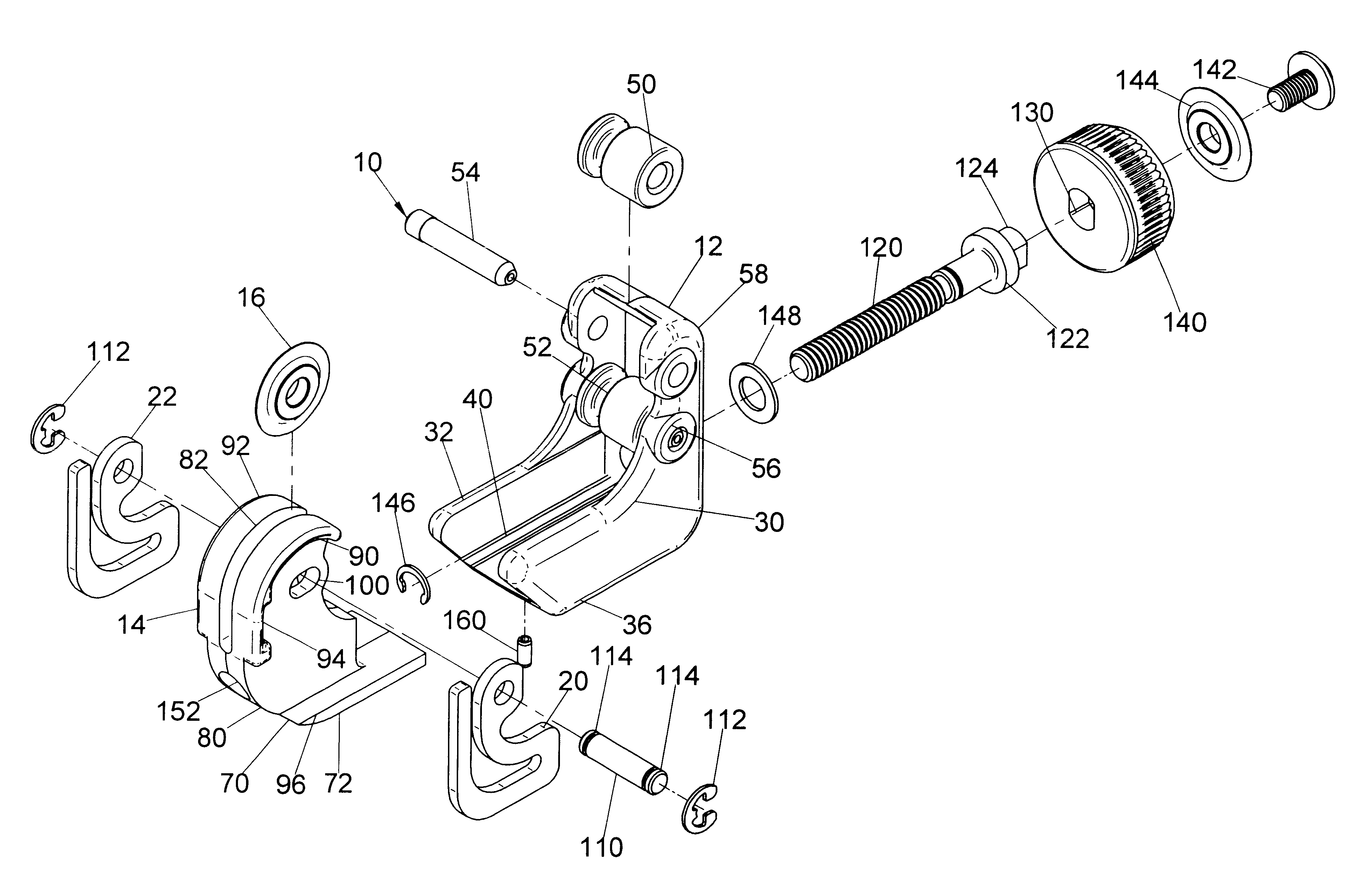
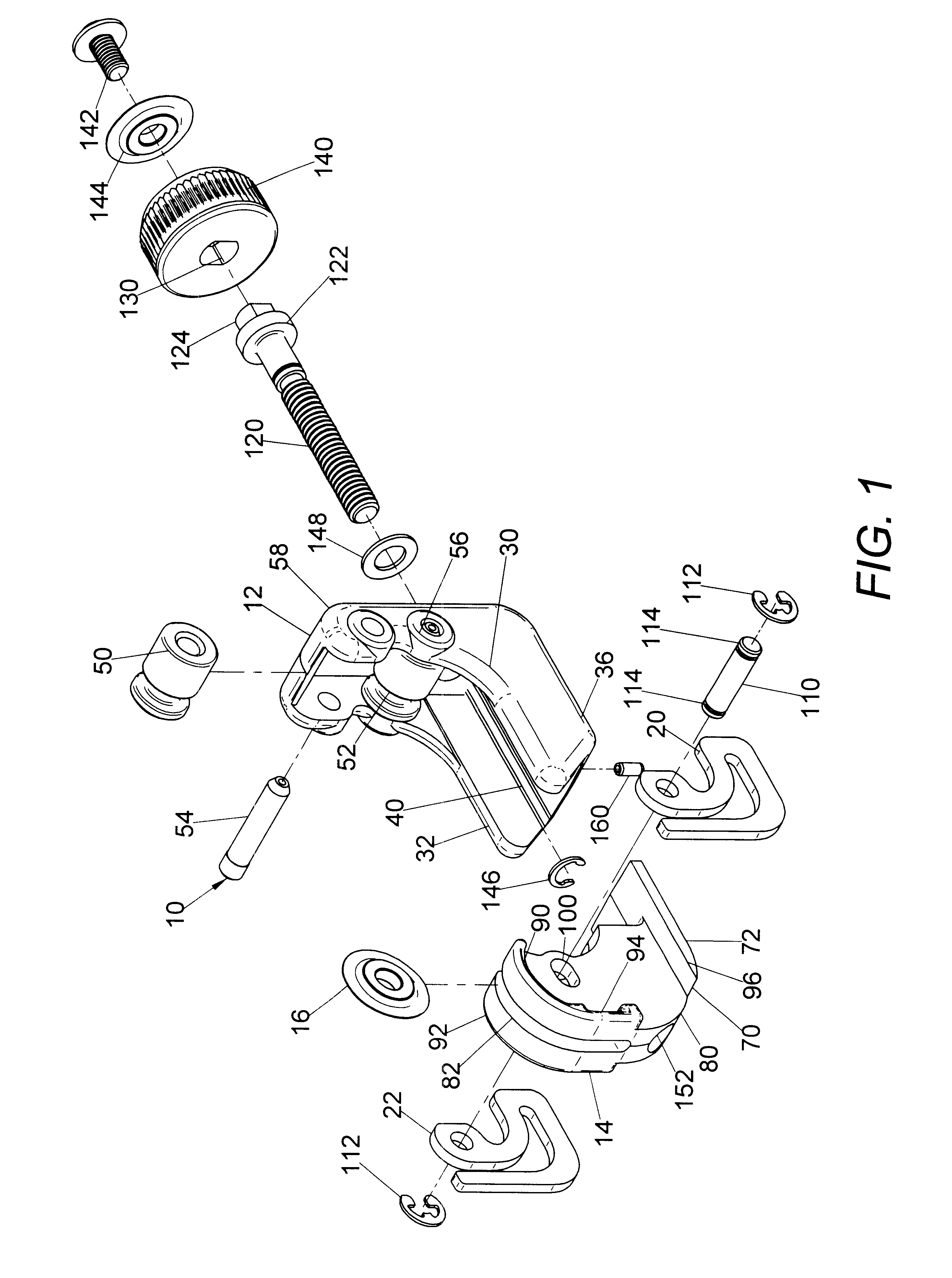
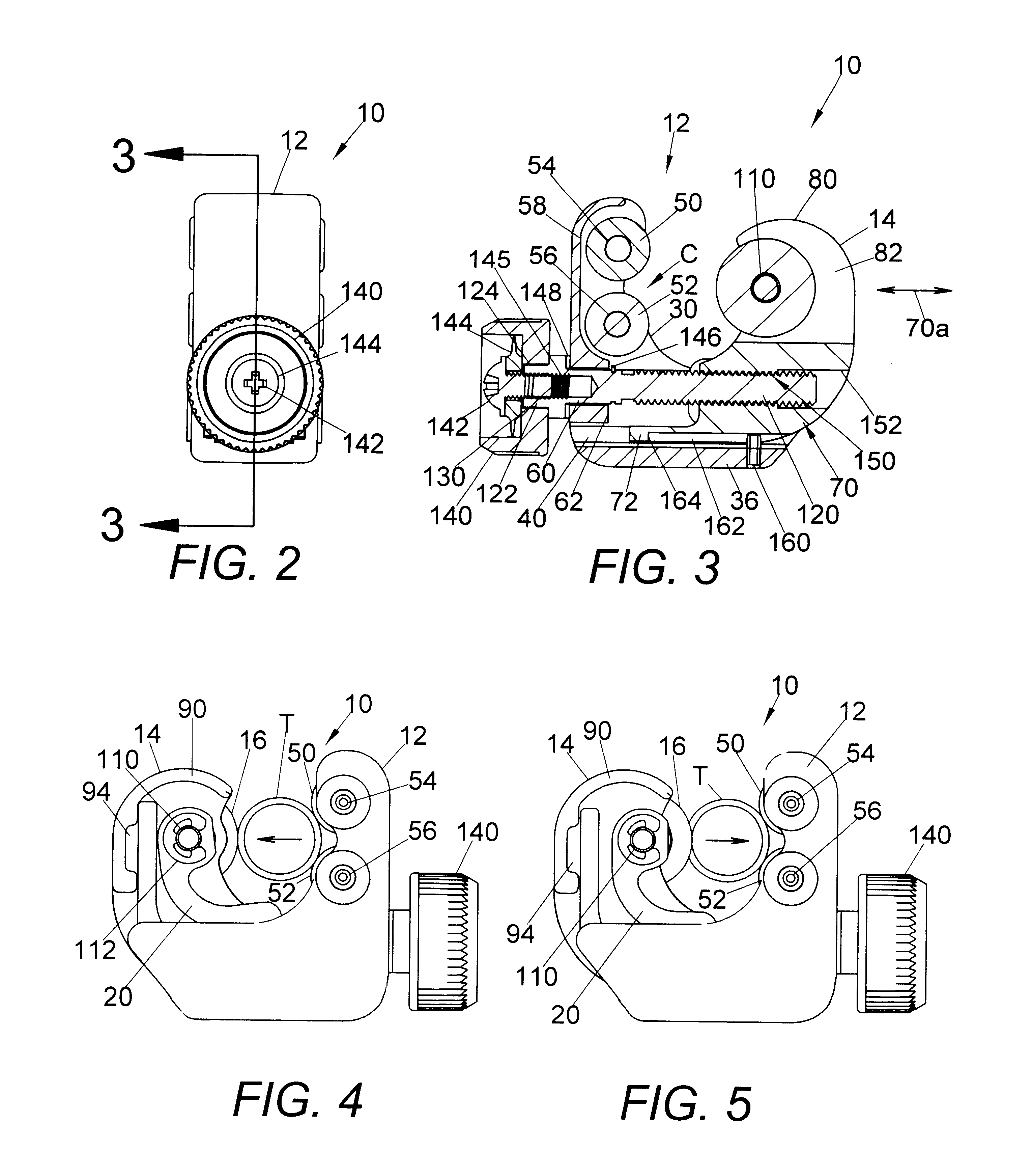
Referring now to the drawings wherein the showings are for the purpose of illustrating a preferred embodiment of the invention only and not for the purpose of limiting same, FIGS. 1-5 show tube cutter 10 having a first frame, or housing, 12 and a second frame, or cutter head, 14 on which is rotatably mounted cutter wheel 16 for cutting tube T, as best shown in FIGS. 4 and 5. During the cutting operation, cutter 10 is assembled onto the tube and rotated, either manually or by an electric driving handle. During rotation, a spring element in the form of two spaced, sheet metal springs 20, 22, as illustrated in FIG. 6, automatically feeds wheel 16 into the tube. In operation, the second frame is slidably moved with respect to the first frame until cutter wheel 16 engages tube T. Thereafter, further movement of the second frame deforms springs 20, 22 until the springs are fully collapsed. The spring provides the cutting force between the cutter wheel 16 and tube T as tool 10 is rotated a...


PUM

PropertyMeasurementUnit
Forceaaaaaaaaaa

Abstract

A tube cutter for cutting a circular tube having a central tube axis, the cutter comprising: a housing with first and second parallel rollers defining a cradle for receiving a tube cut with the tube axis generally parallel to the axes of the rollers, a cutter head reciprocally mounted on the housing for sliding linearly in a direction toward and away from the rollers, the cutter head having a base and an upstanding arm supporting a cutter wheel rotatable about an axis generally parallel to the axes of the rollers and facing the tube in the cradle, a spring element biasing the cutter wheel in the stated direction and toward the rollers, and a threaded shaft between the housing and cutter head, and rotatable to move the cutter head linearly toward the housing, whereby the cutter wheel engages the tube and the spring element creates a cutting force pushing the cutter wheel against the tube for cutting the tube.

Description

The present invention relates to the field of tube cutting and more particularly to a tube cutter having an automatic feed as the cutter is rotated for the purpose of cutting through the tube.A large number of devices exist for rotating a cutter around a tube to cut the tube at the desired position. The present invention relates to a tube cutter wherein the cutter wheel is a wheel biased against the outer surface of the tube to automatically advance or feed the cutter into the tube as the cutter is rotated. A common arrangement for accomplishing this objective is shown in Condon U.S. Pat. No. 2,448,578 and Collier U.S. Pat. No. 5,903,980. A cutter or cutters are carried on a clam shell type frame by a spring element so the clam shell can be assembled over a tube with the cutter biased against the outside surface of the tube. By rotating the frame, the cutter or cutters automatically advances into the tube until the tube is severed. Such devices do not specifically relate to the pres...

Claims


Application Information

Patent Timeline
28 May 2002
Publication
US6393700B1
IPC
B23D21/08; B23D21/00; B23D21/10
CPC
B23D21/08
Inventors
BABB, LARRY F.