Electro-optic apparatus and process for multi-frequency variable refraction with minimized dispersion

a technology of optical apparatus and process, applied in optics, instruments, static indicating devices, etc., can solve the problems of not being able to efficiently use divergent rays, not being able to anticipate nor address the minimization of dispersion, and the complexity of minimizing dispersion in multi-state refractive materials may not be addressed

Inactive Publication Date: 2002-05-28
ALDEN RAY M
View PDF4 Cites 108 Cited by
  • Summary
  • Abstract
  • Description
  • Claims
  • Application Information

AI Technical Summary

Problems solved by technology

But, it has not anticipated nor addressed the minimization of dispersion caused by different refractive indices for different frequencies of electromagnetic radiation passing through the variable liquid crystal.
The complexity of minimizing dispersion in multi-state refractive materials may not have been addressed heretofore because dispersion has not been an issue in the vast majority of applications.
Of course, as anyone who has tried to look at the world through a prism knows, the human eye can not efficiently use divergent rays.
Solving this problem requires much effort in determining precise prism angles that are required for a minimum of eight refractive indices to cause beams to exit at precise trajectories.
Also the lack of beam divergence enables the use of smaller components since the multi-frequency beam stays closer together much longer.
Electro-optic variable focal length lenses have been know in the prior art but they had heretofore not addressed the multi-frequency dispersion problem as solved herein.
Liquid crystal image direction devices heretofore disclosed did not adequately recognize or address the need to minimize dispersion when variably refracting views over distances.

Method used


Image

  • Electro-optic apparatus and process for multi-frequency variable refraction with minimized dispersion
  • Electro-optic apparatus and process for multi-frequency variable refraction with minimized dispersion
  • Electro-optic apparatus and process for multi-frequency variable refraction with minimized dispersion

Examples


Embodiment Construction

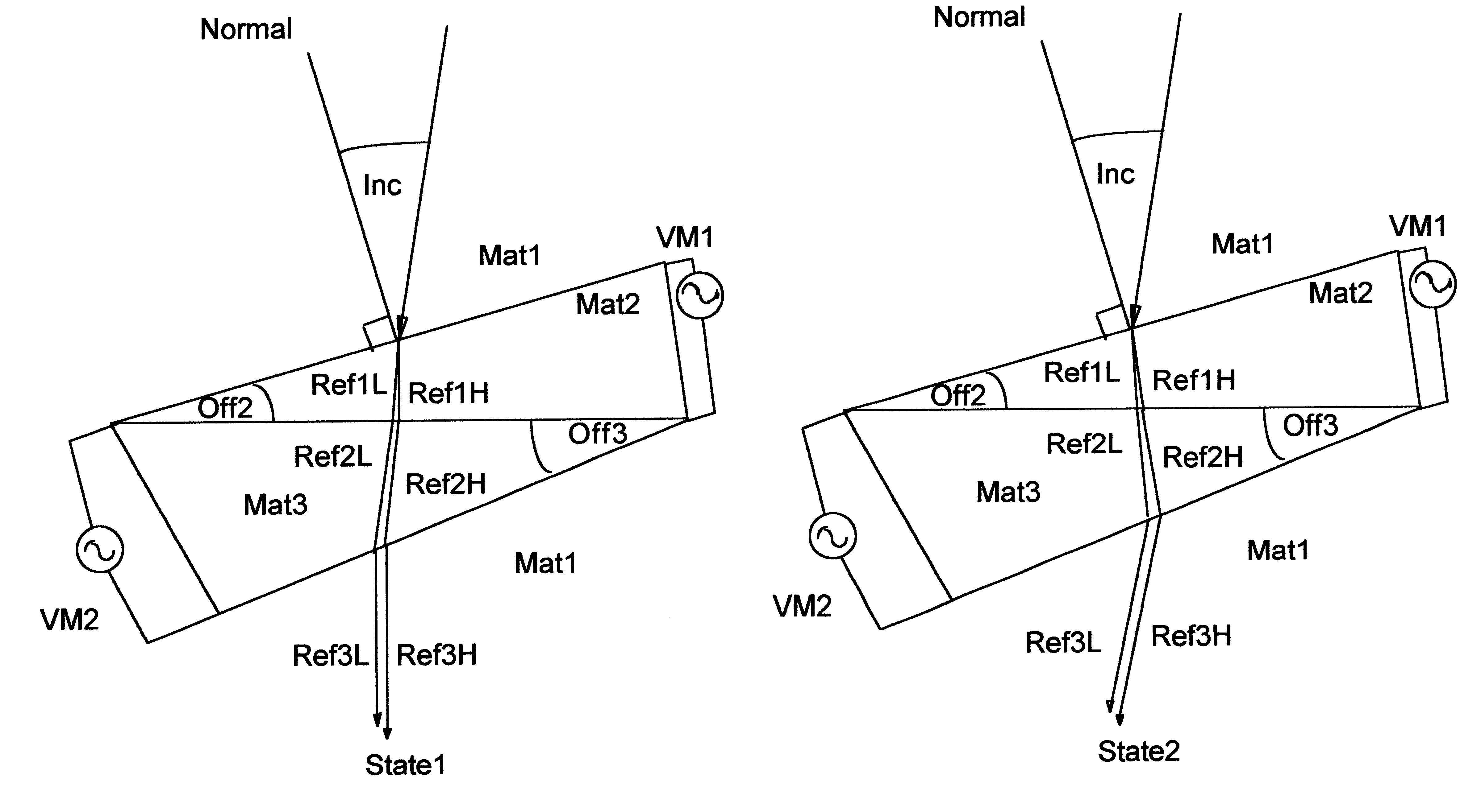
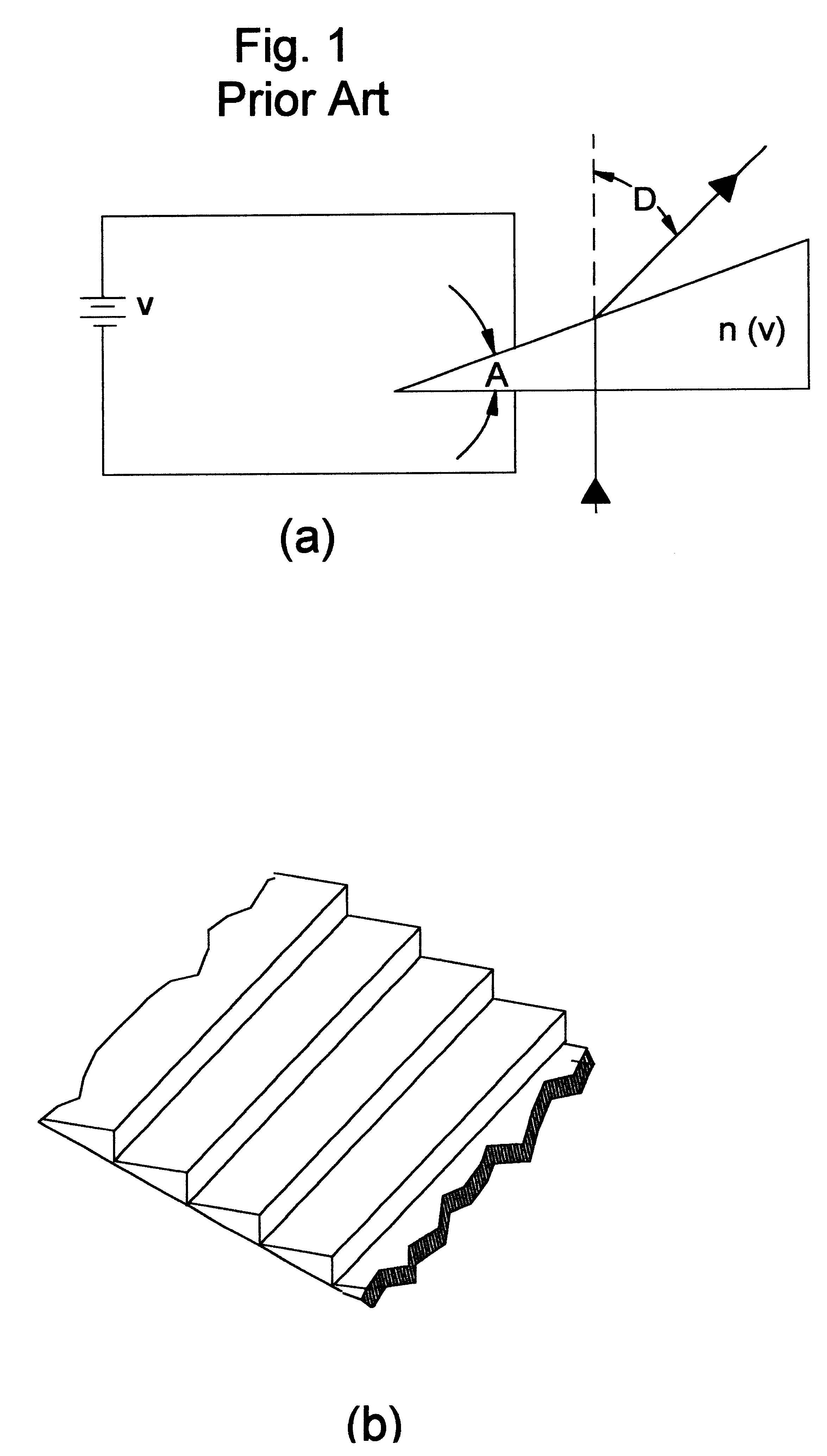
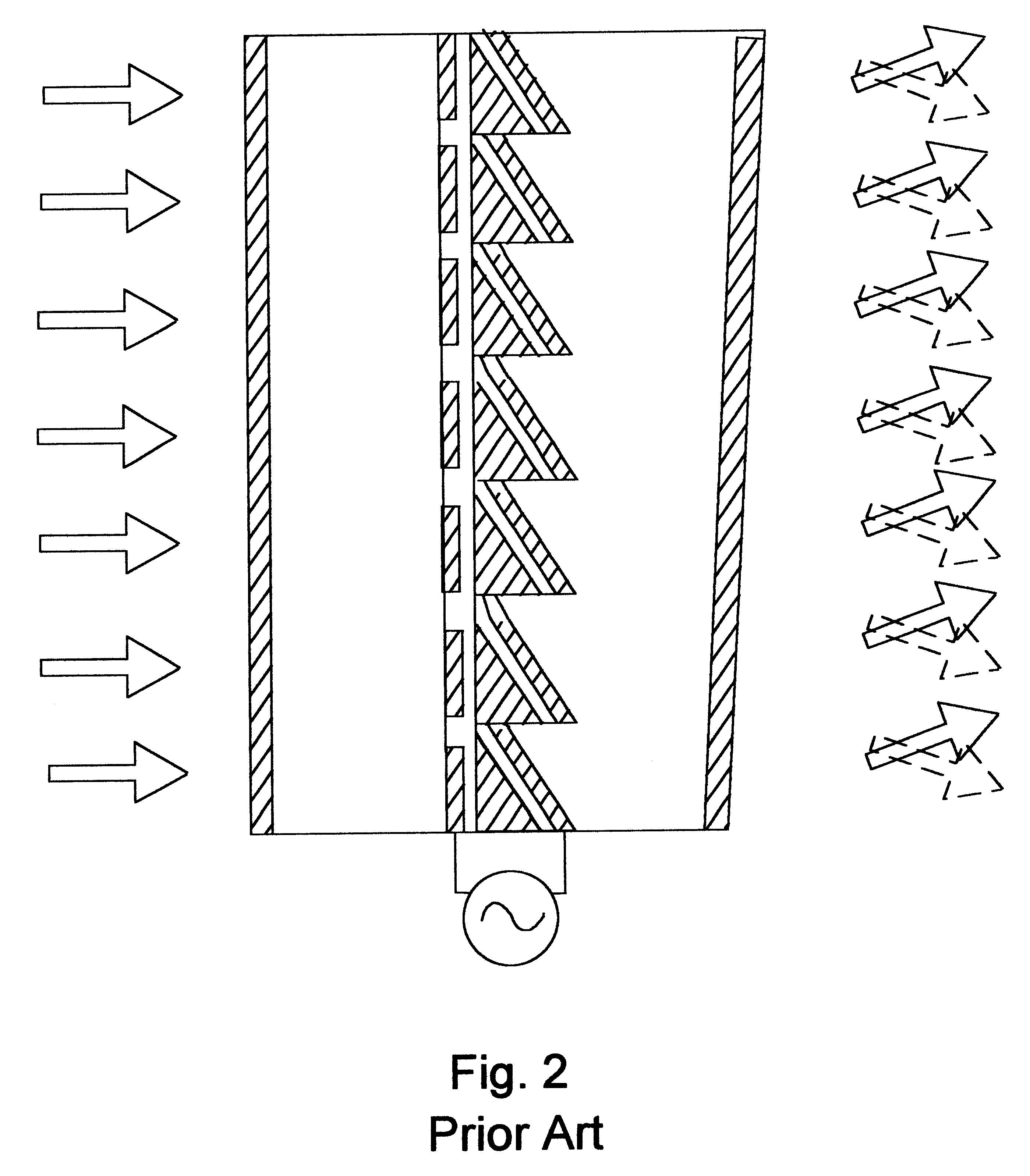
For nearly 30 years, in a multitude of embodiments, the prior art has disclosed changing a refractive index over a range between no and ne as a function of a variable voltage applied to a liquid crystal. FIG. 1a, prior art, U.S. Pat. No. 4,958,914 (Owechko et al., 1990), illustrates a simple circuit schematic for varying the refractive index of an electro-optic material such as a liquid crystal cell with an apex angle of "A" through varying the intensity of an electric field applied thereto. An array of such cells is depicted in FIG. 1b from the same patent. While this and other similar prior art has been used to variably refract light for 30 years, the problem of dispersion has neither been anticipated nor addressed. The complexity of minimizing dispersion in multi-state refractive materials may not have been addressed heretofore because dispersion has not been an issue in the vast majority of applications.

Many applications to date have used single frequency electromagnetic radiati...


PUM

PropertyMeasurementUnit
refractive indexaaaaaaaaaa
dispersion angleaaaaaaaaaa
refractive indicesaaaaaaaaaa

Abstract

The object of the prevent invention is to provide an optical system for producing variable refraction with minimized dispersion. A first material with a first apex angle in a first state and a second material with a second apex angle in a first state produce a first net refraction angle in at least two frequencies of electromagnetic radiation such that the beams that entered parallel exit parallel (to within a controllable tolerance). Said first material with said first apex angle in a second state and said second material with said second apex angle in a second state produce a second net refraction angle in at least two frequencies of electromagnetic radiation such that the beams that entered parallel exit parallel (to within a controllable tolerance).

Description

BACKGROUND--FIELD OF INVENTIONThis invention relates to electro-optic lenses, such as are used for variably bending light. Such lenses have broad applications including directing and switching light within fiber optics applications, focusing light as with optical lenses, and coherent imaging as with windows that are mounted in a building or on a vehicle, or a television or computer monitor screen. Specifically this invention couples electro-optic components (such as liquid crystals) in series such that a first liquid crystal comprising a first apex angle and a second liquid crystal comprising a second apex angle refract light of at least two frequencies simultaneously with minimal spectral dispersion. Moreover, said first and second liquid crystals so configured produce a first net refractive exiting beam angle with minimal dispersion when in a first state and a second net refractive exiting beam angle with minimal dispersion when in a second state. The invention enables switching b...

Claims


Application Information

Patent Timeline
Patent Type & Authority Patents(United States)
IPC IPC(8): G02F1/1333G02F1/13G02F1/1347G02F1/29
CPCG02F1/133371G02F1/13471G02F1/29G02F2203/28G02F2001/291G02F2001/294G02F1/291G02F1/294
Inventor ALDEN, RAY M.
Owner ALDEN RAY M
Why Eureka
Try Eureka