Tuning a narrow band filter for telecommunication applications with an acoustic optical tunable filter

a narrow band filter and optical tunable technology, applied in non-linear optics, instruments, optics, etc., can solve the problems of increasing cost and reliability concerns, unable to achieve the implementation of tunable filters, and the conventional technology of designing and manufacturing tunable filters for telecommunication systems implemented with fiber optics still faces significant technical challenges, and achieves low power consumption tunable

Inactive Publication Date: 2008-01-29
NEOPHOTONICS CORP
View PDF2 Cites 0 Cited by
  • Summary
  • Abstract
  • Description
  • Claims
  • Application Information

AI Technical Summary

Benefits of technology

[0016]It is therefore an object of the present invention to provide a compact, very high resolution (narrow linewidth) and low power consumption tunable filter suitable for telecom DWDM applications and practically for very high-resolution spectroscopic applications such that the above discussed difficulties and limitations may be resolved.
[0018]Another aspect of this invention is to provide a compact and cost effective tunable filter for dynamically configurable cross-connectors and add / drop modules in DWDM applications wherein the filtered channel is implemented as the drop channel. The tunable filter is further implemented as an add module when the optical transmission is projected in a reverse direction wherein the filtered channel is added to the optical transmission.
[0019]Another aspect of this invention is to provide a tunable filter with a small form factor to fit into tight space. Furthermore, a reduced production cost of such compact package makes it practical to manufacture in a large volume.
[0020]Another aspect of this invention is to provide a tunable filter to satisfy the demands of a fast wavelength tuning speed, low power consumption and wide wavelength tuning range. These requirements are satisfied by designing a highly effective acousto-opto beam deflector (AOD) device which capable to deflect small aperture beam (<500 um in diameter) whose only purpose is to deflect the light of practically all the wavelengths in a single direction simply by means of Bragg's diffraction. For a system provided with an AOD with a small aperture, the output beam from the AOD is essentially the same as the incident beam. The deflected angle is determined and tuned by the frequency of RF signal driving acoustic wave in the crystal. The narrow spectral bandwidth of selected DWDM channel is achieved by a combination of a beam expander and a set of fixed diffraction gratings, preferred Littrow-type, to have a high throughput (low insertion loss).
[0021]Another object is to provide a narrow spectral bandwidth tunable filter for precise channel performance monitoring and other related applications. Spectral resolution is improved by using a grazing-incidence grating, together a beam expander.
[0023]In this invention, besides the advantages achieved by combining the acoustic-optic tuning and high dense diffraction gratings, the two key components to provide a high performance tunable filter for DWDM applications are the beam expander and the directional tuning acousto-optic crystal. The beam expander generates a large beam size on the grating, which results in a high spectral resolution, while it keeps the input beam in the acousto-optic crystal small. The optical system thus enables the use of a compact crystal and leads to low cost production. A patented acousto-optic crystal disclosed in a prior patent application by a common inventor of this Application is implemented in this invention to deflect a broad spectral band beam with minimal dispersion. Thus it acts solely as a beam-deflecting device, and the deflecting angle is a function of the frequency of RF driving signal only, independent of the optical frequency of the incident beam.

Problems solved by technology

Conventional technologies for designing and manufacturing tunable filters for telecommunication systems implemented with fiber optics are still faced with significant technical challenges.
Under most circumstances for a DWDM system, a tunable filter is required to have low insertion loss, narrow bandwidth, flat passband, large tuning range, fast tuning speed, compact size and low driving power.
Due to the technical difficulties in meeting these highly demanding system requirements, implementations of tunable filters are still not achievable in most cases even that a tunable filter can provide significant advantages of more operational flexibility, simplified system configurations and significant cost savings.
However, narrower bandwidth often is achieved in the expense of large device size, high electrical power consumption and complexities of internal structure, thus raise cost and reliability concern and limits its practical applications in the telecommunication systems.
Thermal tuning is slow and can provide only limited tuning range due to its impractical temperature elevation.
Thermal tuning also limits the tuning resolution.
Mechanical tuning is very sensitive to shock and vibration and is a very unstable method for telecom applications.
For very narrow band optical power monitoring applications where filter bandwidth is <0.1 nm and still smaller preferred, the requirements for the AO crystal is in the order of 20 mm cubes and will consume watts of electrical power along with large size making it very impractical for telecom applications.
However, a large beam size on AOTF demands a large size of the acousto-optic material, which puts serious limitations on practical applications: high RF power to drive the crystal and then high cooling capacity needed; large crystal volume leading to high cost of manufacturing and unfit to limited space in telecom applications.2. Since the diffraction grating determines the spectral bandwidth, the filter spectral shape is essentially proportional to
On the other hand, the high spectral resolution from the diffraction grating requires a large beam size on the grating.
Therefore, there is an inherent trade-off between tuning speed and spectral resolution in the prior art design.4. Wavelength tuning range limitation is related to RF tuning range and can become very limiting in practical implementations.

Method used


Image

  • Tuning a narrow band filter for telecommunication applications with an acoustic optical tunable filter
  • Tuning a narrow band filter for telecommunication applications with an acoustic optical tunable filter
  • Tuning a narrow band filter for telecommunication applications with an acoustic optical tunable filter

Examples


Embodiment Construction

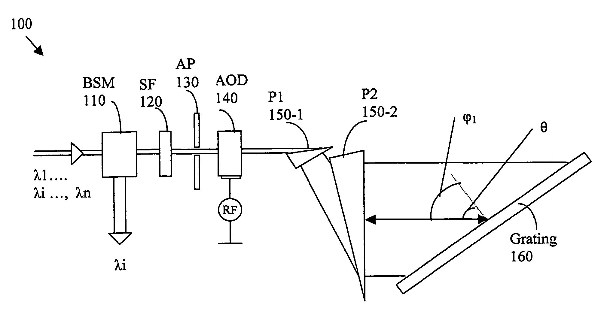
[0030]FIG. 2 shows a functional block diagram for a tunable narrow band filter 100 of the present invention. The tunable filter 100 includes a beam separation polarization and handling module (BSM) 110 to receive a multiple channel optical signal comprising signals of wavelengths λ1, λ2, λ3, . . . , λn. An optical signal λi is separated by the BSM and the signals of remainder channels pass through to project to a shaping filter (SF) 120. Depending on the different applications, the BSM module 110 can be a directional coupler, wavefront splitter, polarization splitter, circulator, or any combination of these devices plus other components. Its function can be drop, add, or drop and add of selected channels.

[0031]The SF 120 has a periodic filtering grid coincides and matches with the ITU (International Telecommunication Union) grid spacing to shape-match that of the grating filter as that will be discussed below for producing flat-top filtering profile. The filtered signals passing thr...


PUM

PropertyMeasurementUnit
wavelength resolutionaaaaaaaaaa
wavelength rangeaaaaaaaaaa

Abstract

An optical tunable filter that includes an tunable acousto-opto deflector (AOD) for deflecting a broad band beam to an expander for projecting the broad band beam to a set of grating for generated a tuned output beam corresponding to a deflection from the AOD and a wavelength resolution of the set of gratings. The AOD further includes an RF driver for tuning the AOD with an RF driving signal. The AOD further comprises a directional tuning acousto-optic crystal. The optical beam expander further includes a first and a second beam expanding prisms that composed of a material suitable for a dense wavelength division multiplexing (DWDM) application over a wavelength range covering S, C and L bands.

Description

[0001]This is a Continuous-In-Part (CIP) Application of a previously filed application with Ser. No. 10 / 744,987 filed on Dec. 23, 2003 now U.S. Pat. No. 7,057,799, application Ser. No. 10 / 744,987 is a Continuation-In-Part application of Ser. No. 10 / 428,899 filed on May 3, 2003 now U.S. Pat. No. 6,930,819, by one of the Applicants of this invention. Application Ser. Nos. 10 / 428,899 and 10 / 744,987 are hereby incorporated by reference in this Patent Application.FIELD OF THE INVENTION[0002]The present invention relates generally to apparatuses and method for providing filters for optical fiber telecommunication systems. More particularly, this invention relates to new configurations and methods for providing tunable narrow band filters implemented with acoustic optical tunable deflector (AOD) with a beam expander to project an expanded beam to a set of diffraction gratings with dense resolution to satisfy highly demanding specifications for a tunable filter for practical implementation ...

Claims


Application Information

Patent Timeline
Patent Type & Authority Patents(United States)
IPC IPC(8): G02F1/33G02F1/11
CPCG02F1/33G02F2203/055
Inventor CHU, RAYMOND R.
Owner NEOPHOTONICS CORP
Why Eureka
Try Eureka