Dynamic pressure bearing apparatus and method for manufacturing thereof

a technology of dynamic pressure bearings and bearings, which is applied in the manufacture of sliding contact bearings, stator/rotor bodies, instruments, etc., can solve the problems of difficult to obtain sufficient length for connecting hubs, difficult to provide accurate disk mounting, and inability to obtain high accuracy of disk mounting surfaces, etc., to achieve the effect of reducing cost and increasing yield

Inactive Publication Date: 2002-06-04
NIDEC CORP
View PDF5 Cites 17 Cited by
  • Summary
  • Abstract
  • Description
  • Claims
  • Application Information

AI Technical Summary

Benefits of technology

It therefore is an object of the present invention to provide a dynamic pressure bearing apparatus and a method for manufacturing thereof in which vibration of a hub can be recognized and controlled in the first stage of an assembly process such that accuracy therein is increased and the yield is increased for a lower cost.
It is a further object to provide a dynamic pressure bearing apparatus and a method for manufacturing thereof in which oil as a lubricant fluid can be easily inserted and oil leakage is minimized.
To achieve the above objects, a dynamic pressure bearing apparatus is provided in which a hub is fixed to a rotatable shaft and a disk mounting surface of the hub is processed, wherein the rotatable shaft is inserted into a sleeve. The apparatus is provided with high accuracy as compared to conventional technology in which the vibration of the hub is adjusted at the end of the assembly process. Yield is improved, and the accuracy is guaranteed in the pre-process so that assembly errors and manufacturing cost can be decreased.
In accordance with aspect of the invention, a space between a hub and the end surface of a sleeve is established larger than the bearing space of the dynamic pressure bearing, and is formed to widen outwardly in relation to the side of the dynamic pressure bearing. Therefore, oil can be readily inserted through the relatively large space to the dynamic pressure bearing. Also, since the space between the hub and the end surface of the sleeve is formed to widen outward, cleaning after insertion of the oil is made easy.

Problems solved by technology

Therefore, one may not be able to obtain high accuracy of disk mounting surface 31 of hub 30 for vibration or deviation in the axial direction in relation to the rotational center of rotatable shaft 21.
This is another reason why it is difficult to provide accuracy of disk mounting surface 31 for vibration in the axial direction.
Further, in the case of a short length in the axial direction with a thin bearing, it is difficult to obtain sufficient length for connecting hub 30 and rotatable shaft 21.
As a result, bonding strength is not sufficient, when impact is applied, the product is deformed such that desired characteristics are not obtained.
However, resolving the problem of vibration or deviation by cutting while rotating with an outside drive after assembling the dynamic pressure bearing as described above causes shortening of the life of the bearing due to contacts among parts thereof.

Method used


Image

  • Dynamic pressure bearing apparatus and method for manufacturing thereof
  • Dynamic pressure bearing apparatus and method for manufacturing thereof
  • Dynamic pressure bearing apparatus and method for manufacturing thereof

Examples


Embodiment Construction

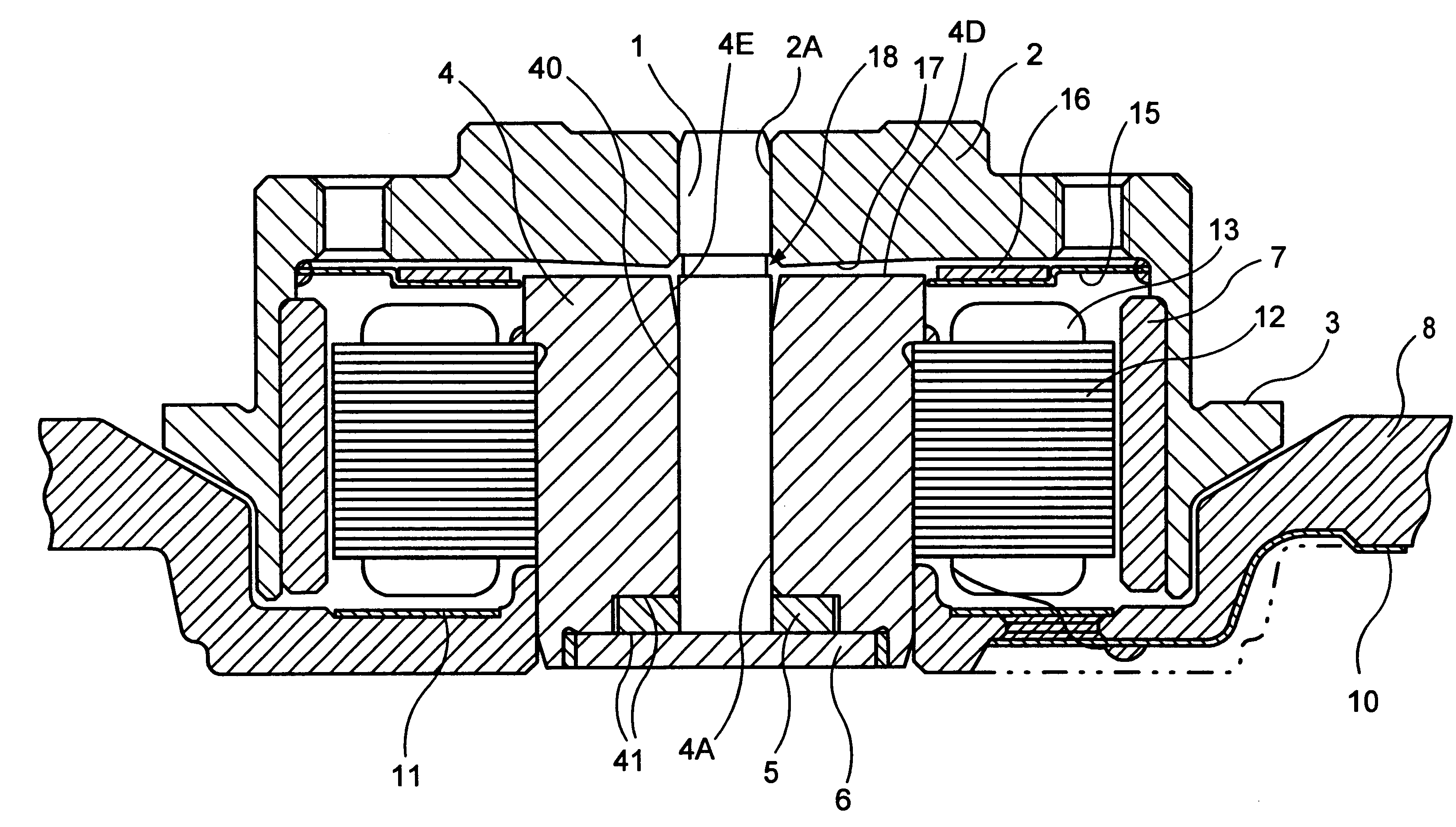
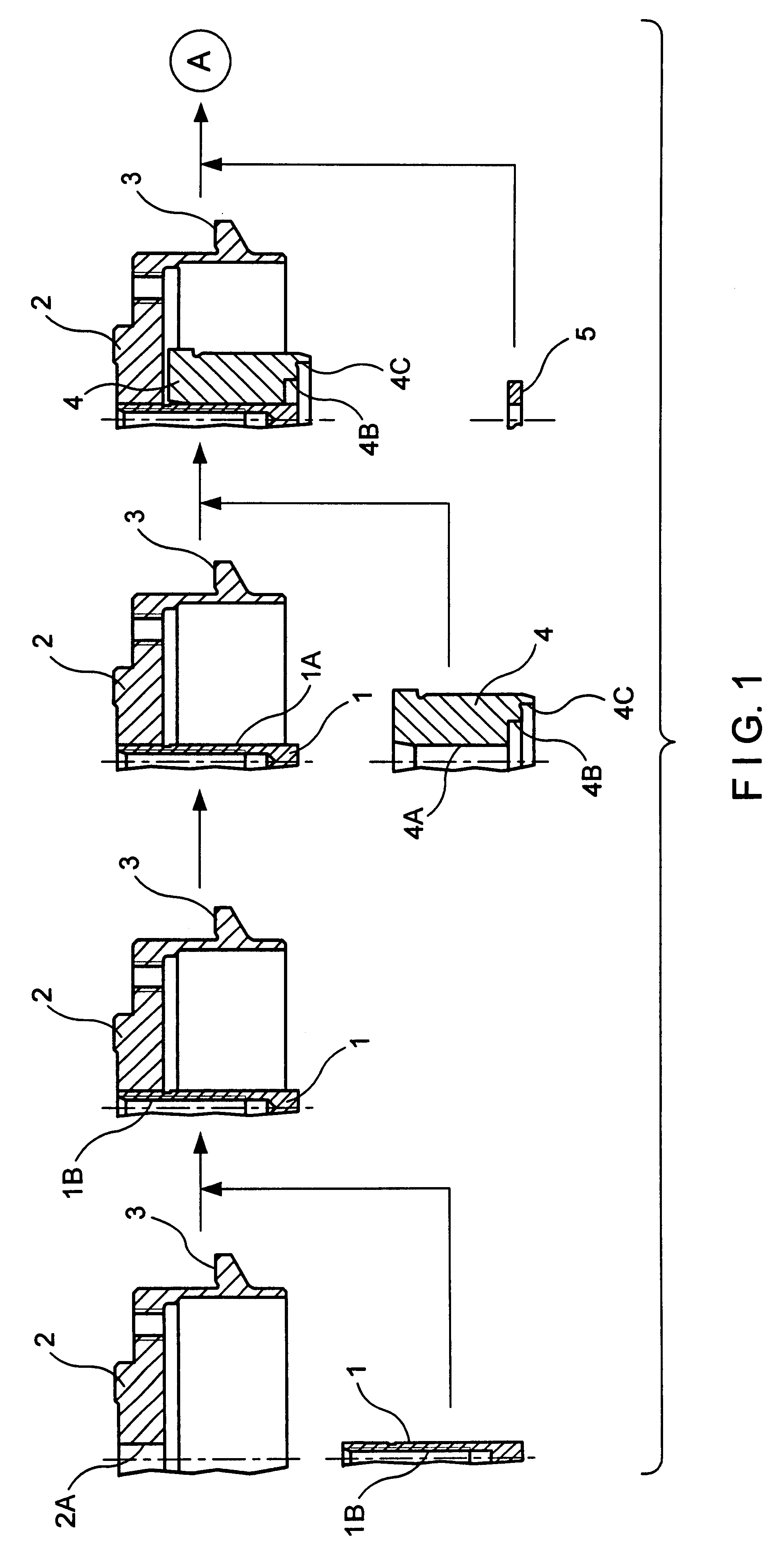
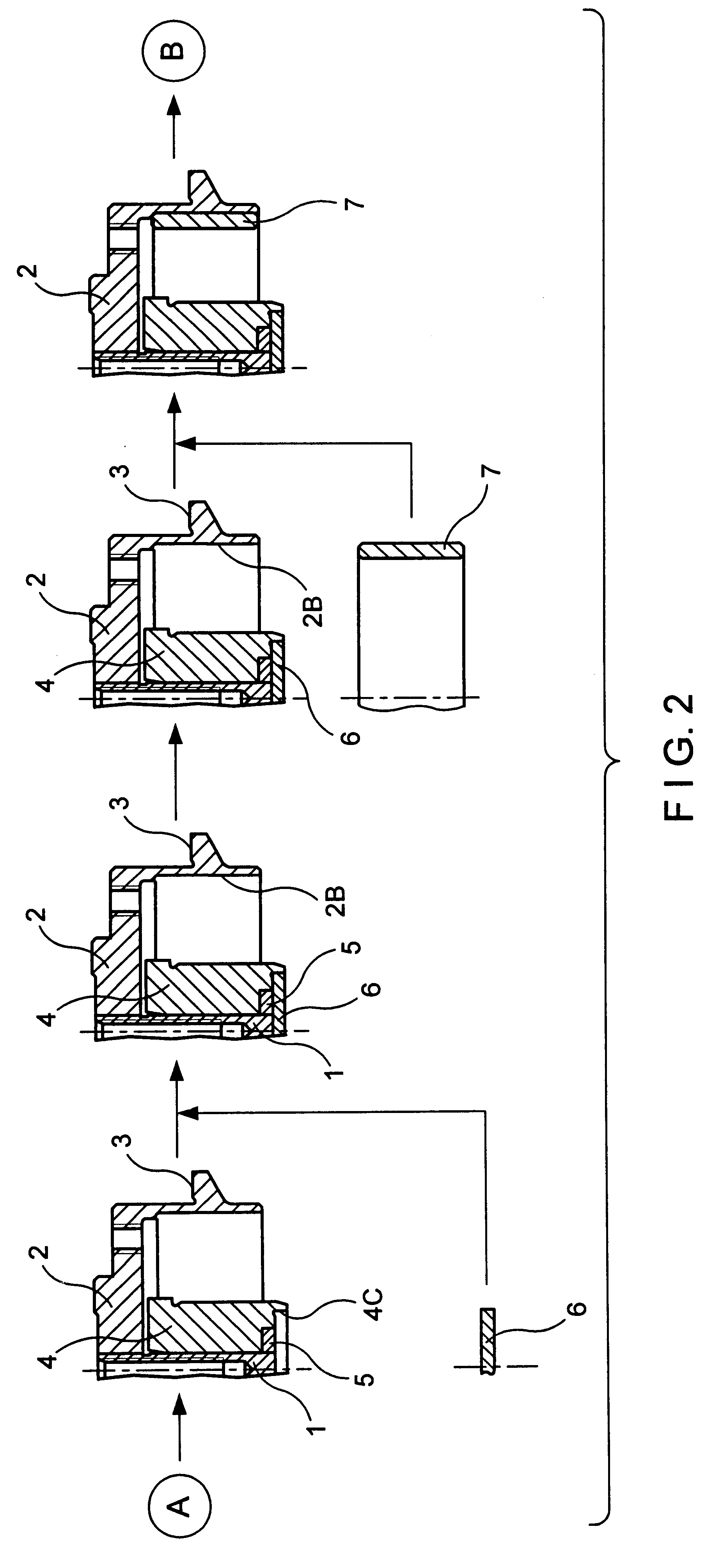
The following describes a dynamic pressure bearing apparatus and a method for manufacturing thereof of the present invention in relation to examples of a disk drive apparatus shown in FIGS. 1-5. Configurations of the disk drive apparatus shown in FIGS. 1-4 only indicate a right half thereof in relation to a rotational axis of a motor.

FIG. 1, as the first process, the top end of rotatable shaft 1 with a screw hole at its center is press-fitted into center hole 2A of hub 2 with a shape of a reversed cup wherein the two parts are fixed to each other by laser welding. Hub 2 is for mounting a disk such as a hard disc; the upper surface of a flanging portion, which is integrally formed around the outer circumference of cylindrical body of hub 2, is disk mounting surface 3. It is desirable that rotatable shaft 1 and hub 2 can be firmly fixed to each other only by press fitting. However, the length needed for press fitting tends to decrease as a disk drive apparatus is miniaturized and its ...


PUM

PropertyMeasurementUnit
thicknessaaaaaaaaaa
distanceaaaaaaaaaa
radial dynamic pressureaaaaaaaaaa

Abstract

A dynamic pressure bearing apparatus has a rotatable shaft to which a hub is mounted, a disk fixed to the hub, a sleeve which supports the rotatable shaft, and a dynamic pressure bearing formed between the rotatable shaft and the sleeve. The rotatable shaft is rotatably supported by the dynamic pressure bearing. The dynamic pressure bearing apparatus is manufactured by integrating the hub and the rotatable shaft by fixing the hub and shaft to each other, processing the disk mounting surface of the hub after integration, such that relative accuracy between the rotatable shaft and the disk mounting surface can be obtained, and then assembling the rotatable shaft to the sleeve.

Description

The present invention relates to a dynamic pressure bearing apparatus applicable to a motor for a hard disk drive as well as a method for manufacturing such dynamic pressure bearing apparatus. More particularly, the present invention related to a dynamic pressure bearing apparatus used to increase the rotational accuracy of a hub to which a rotational body such as a disk is mounted.As is known, a dynamic pressure bearing apparatus includes a shaft and a sleeve which rotate in relation to each other. As the apparatus starts rotating at a high speed, dynamic pressure is generated by the dynamic pressure generating grooves that are formed, for example, on the bearing surface. The rotor rotates with high accuracy due to the stiffness of the bearing. By applying such an apparatus as a bearing apparatus in a motor for a hard disk drive, high recording density can be obtained. However, further improvement in recording density is demanded and therefore an increase in rotational accuracy is ...

Claims


Application Information

Patent Timeline
Patent Type & Authority Patents(United States)
IPC IPC(8): B21D53/10F16C33/10F16C33/14F16C33/04H02K15/03H02K15/14H02K5/16H02K21/22F16C17/10
CPCB21D53/10F16C17/026F16C33/107F16C33/14H02K15/14H02K15/03H02K5/163Y10T29/49012H02K21/22Y10T29/49025Y10T29/49696Y10T29/49639
Inventor SAICHI, MASAYOSHIGOMYO, MASATO
Owner NIDEC CORP
Why Eureka
Try Eureka