However, the motors typically found on sport fishing boats are not well suited to achieve the slow boat speeds that effective trolling often demands.
Specifically, the typical outboard or inboard / outboard motor is incapable of being throttled down low enough to achieve an effective trolling speed.
The problem of achieving effective trolling speeds with boat motors is not a new one and has plagued fishermen for some time.
While attempts have been made to resolve this problem, none of these attempts has been completely effective or satisfactory.
While trolling motors are effective in permitting a fisherman to propel the boat through the water at an effective trolling speed, they are problematic in several regards.
First, trolling motors can be rather expensive.
This problem is particularly acute with relatively larger boats which, because of their size, require relatively larger trolling motors to move the boat at an effective trolling speed.
Thus, the fisherman who wants to use his boat for trolling may be forced to incur a significant expenditure in order to do so.
A related problem concerns the maintenance associated with a
trolling motor.
In particular, use of an additional motor will necessarily increase the amount of time and money spent on maintenance.
Thus, the costs associated with a
trolling motor are not limited solely to purchase costs but also include maintenance costs as well.
Thus, a fisherman who changes locations frequently throughout the fishing day is forced to spend a significant amount of
time switching back and forth between the trolling motor and the boat motor.
Clearly, this detracts from the amount of time the fisherman has available for fishing.
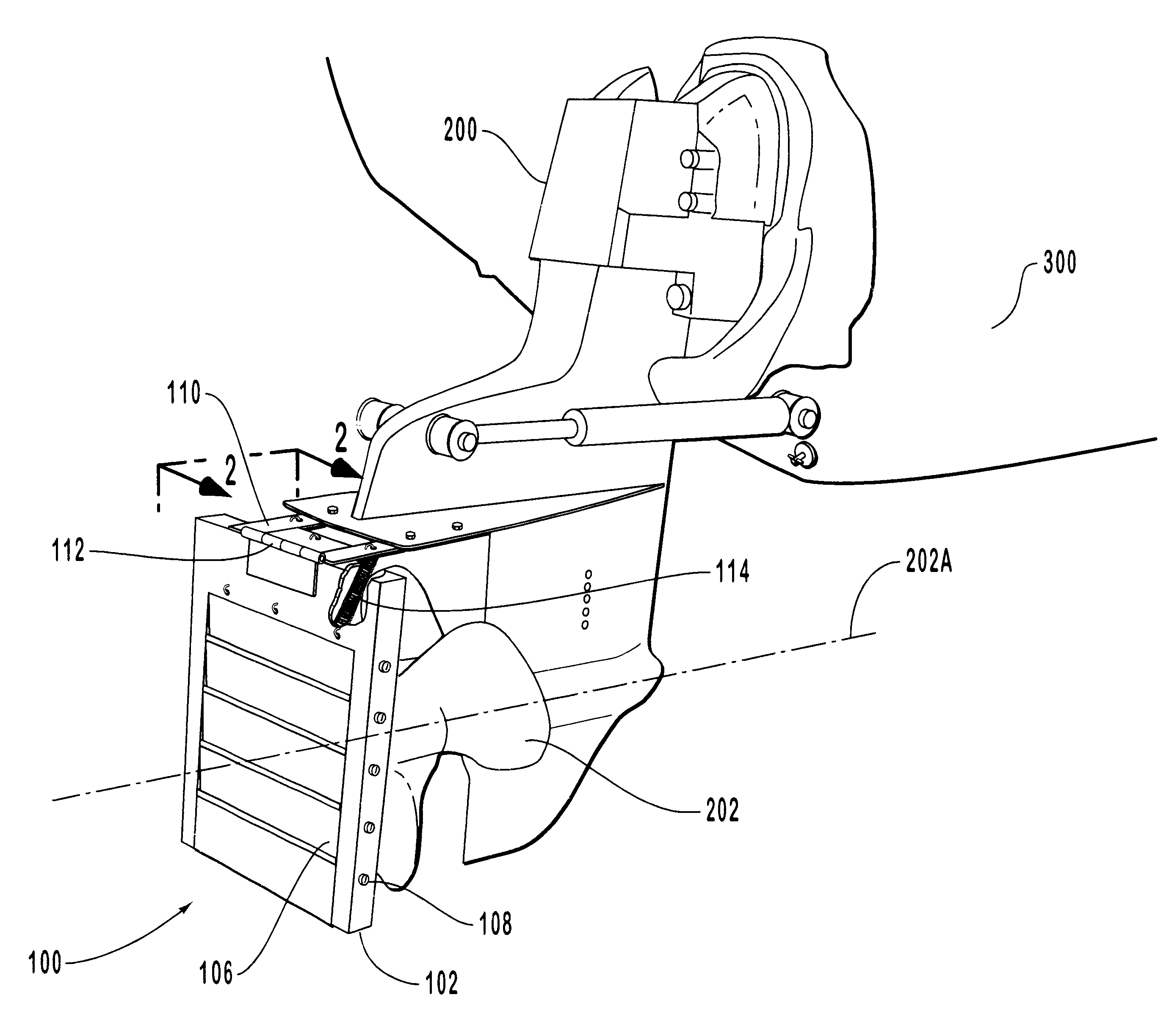
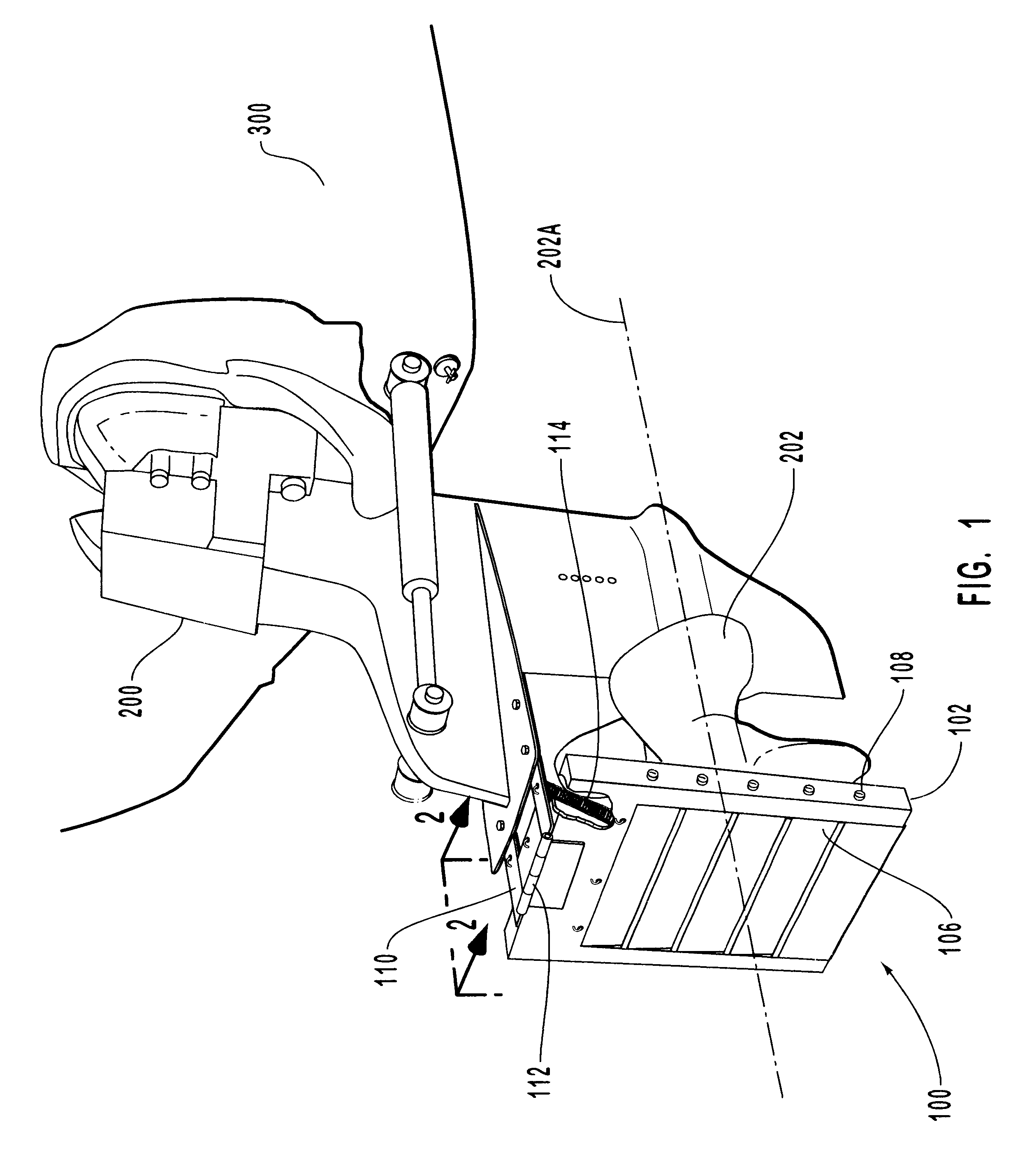
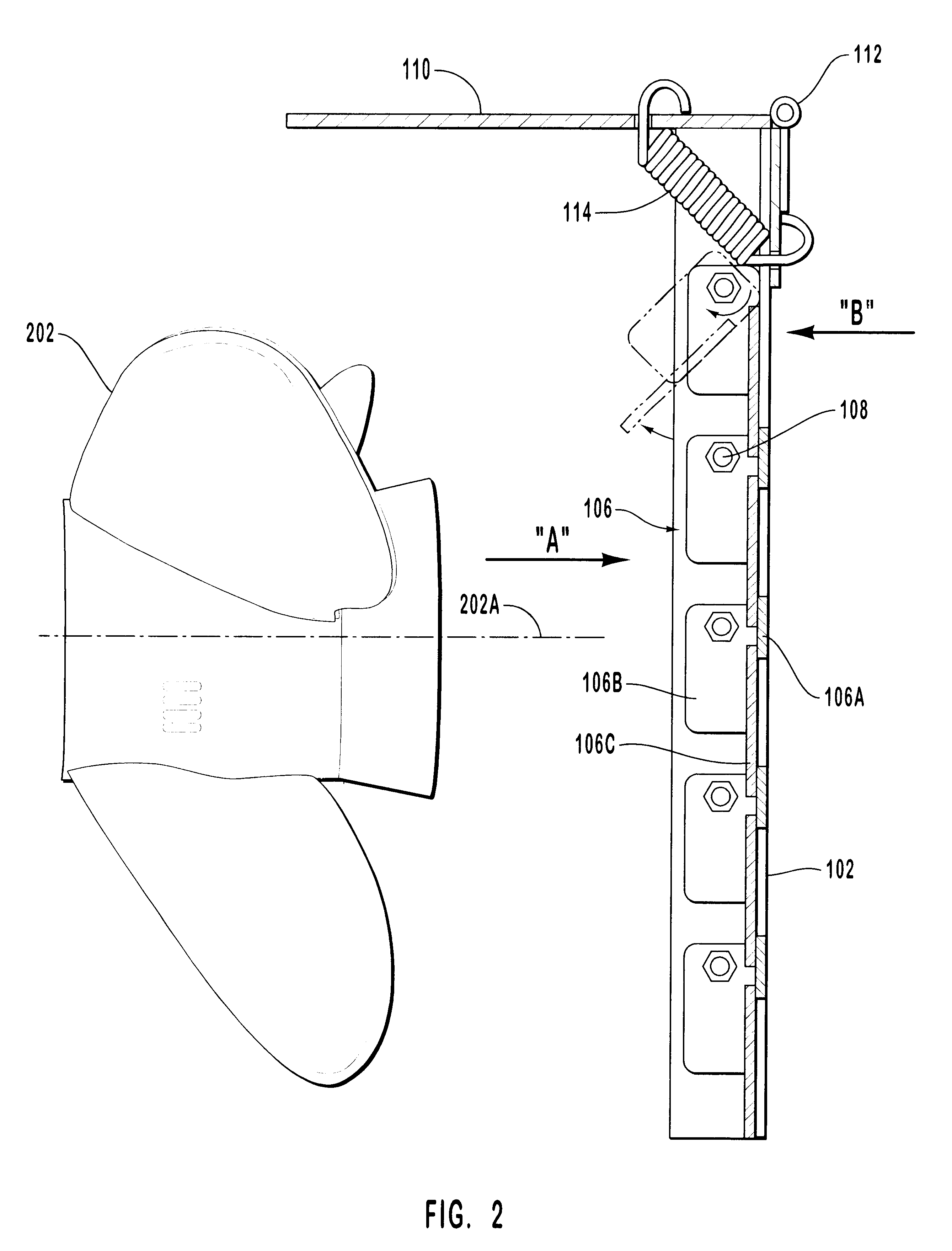
While the use of trolling plates has thus proven effective in assisting boat motors to achieve effective trolling speeds, known trolling plates and the trolling plate deployment mechanisms have proven problematic.
One significant problem with many known trolling plates is that they are mechanically complex and utilize a large number of
moving parts.
Mechanical complexity clearly contributes to increased production costs for these units.
More importantly, however, mechanical complexity increases the likelihood of an operational malfunction.
This problem becomes particularly acute in a marine environment where the mechanism is exposed to the corrosive effects of
seawater.
Also, the presence of a multitude of interconnected and
moving parts makes these trolling plate assemblies more susceptible to damage in the event of an
impact.
Another
disadvantage of known trolling plates is that they do not automatically position themselves, but require operator intervention in order for them to be deployed to the trolling position and / or to the inoperative position.
At best, this arrangement is inconvenient.
At worst, these designs are dangerous, particularly where the operator is maneuvering the boat in close quarters and sudden accelerations could increase the likelihood of a collision.
Again, this type of design is at least inconvenient because it requires action on the part of the boat operator.
This problem becomes particularly acute where the boat operator is the sole occupant of a boat, because operation of the trolling plate could prove to be a dangerous
distraction when the boat is being operated in heavy seas, in areas congested with boats, and / or in areas where there are dangerous natural obstacles.
For at least the reasons stated elsewhere herein, the requirement of manual operation to deploy the trolling plate to a trolling position is undesirable.
Finally, damage to trolling plates is likely to occur where the trolling plate design requires manual operation to move the trolling plate upward to an inoperative position.
In particular, if the trolling plate is locked in the trolling position or stuck in the trolling position due to a malfunction of the deployment mechanism, the trolling plate is likely to bend and / or break when the boat accelerates to and / or maintains a
high rate of speed.
Note that this problem can also result where the boat operator simply forgets to move the trolling plate to the inoperative position prior to high speed running.
Clearly, a broken or bent trolling plate will be generally ineffective in reducing boat speed to the rate required for effective trolling.
Further, a bent or broken trolling plate will necessitate the expense of replacement.
At least one problem with these types of trolling plates concerns their effect on boat control and maneuverability.
While the trolling plate clearly produces a desirable effect when the boat is traveling in a forward gear, the trolling plate is detrimental to boat control and maneuverability when the boat is traveling in a reverse gear.
Specifically, the trolling plate, biased as it is into the trolling position, tends to impede the inflow of water to the boat motor propeller in such a way that reverse motion of the boat is significantly hindered.
This is particularly problematic in situations where the use of reverse gear is required for maneuvering near docks, other boats and / or obstructions in the water.

