Multiplexed fluorescent detection in microfluidic devices

a microfluidic device and multi-color technology, applied in the field of systems for detecting fluorescent signals in capillary arrays, can solve problems such as limited diffraction performan

Inactive Publication Date: 2002-06-04
MONOGRAM BIOSCIENCES
View PDF4 Cites 363 Cited by
  • Summary
  • Abstract
  • Description
  • Claims
  • Application Information

AI Technical Summary

Problems solved by technology

They are designed to be small, yet stil

Method used


Image

  • Multiplexed fluorescent detection in microfluidic devices
  • Multiplexed fluorescent detection in microfluidic devices
  • Multiplexed fluorescent detection in microfluidic devices

Examples


Embodiment Construction

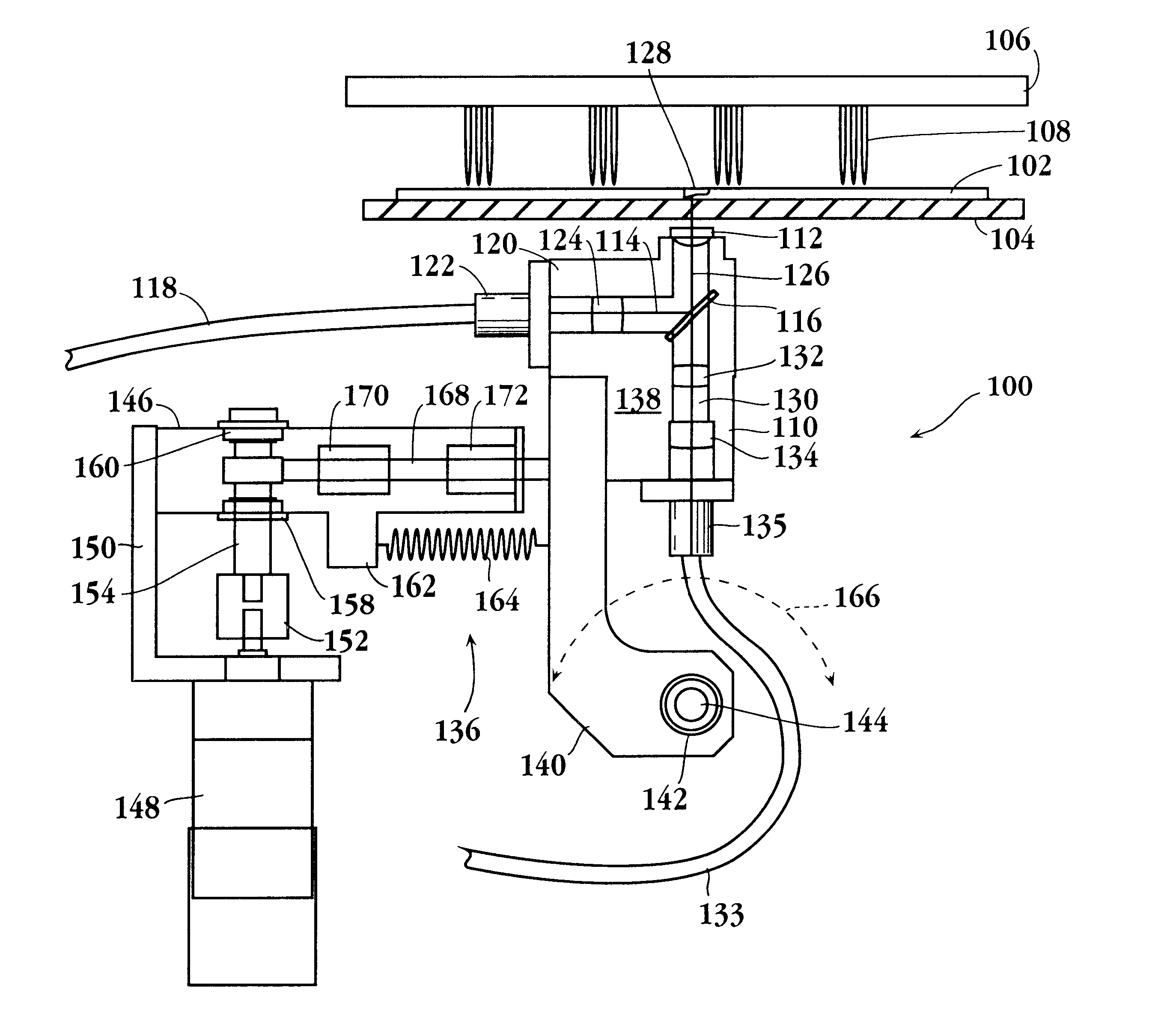
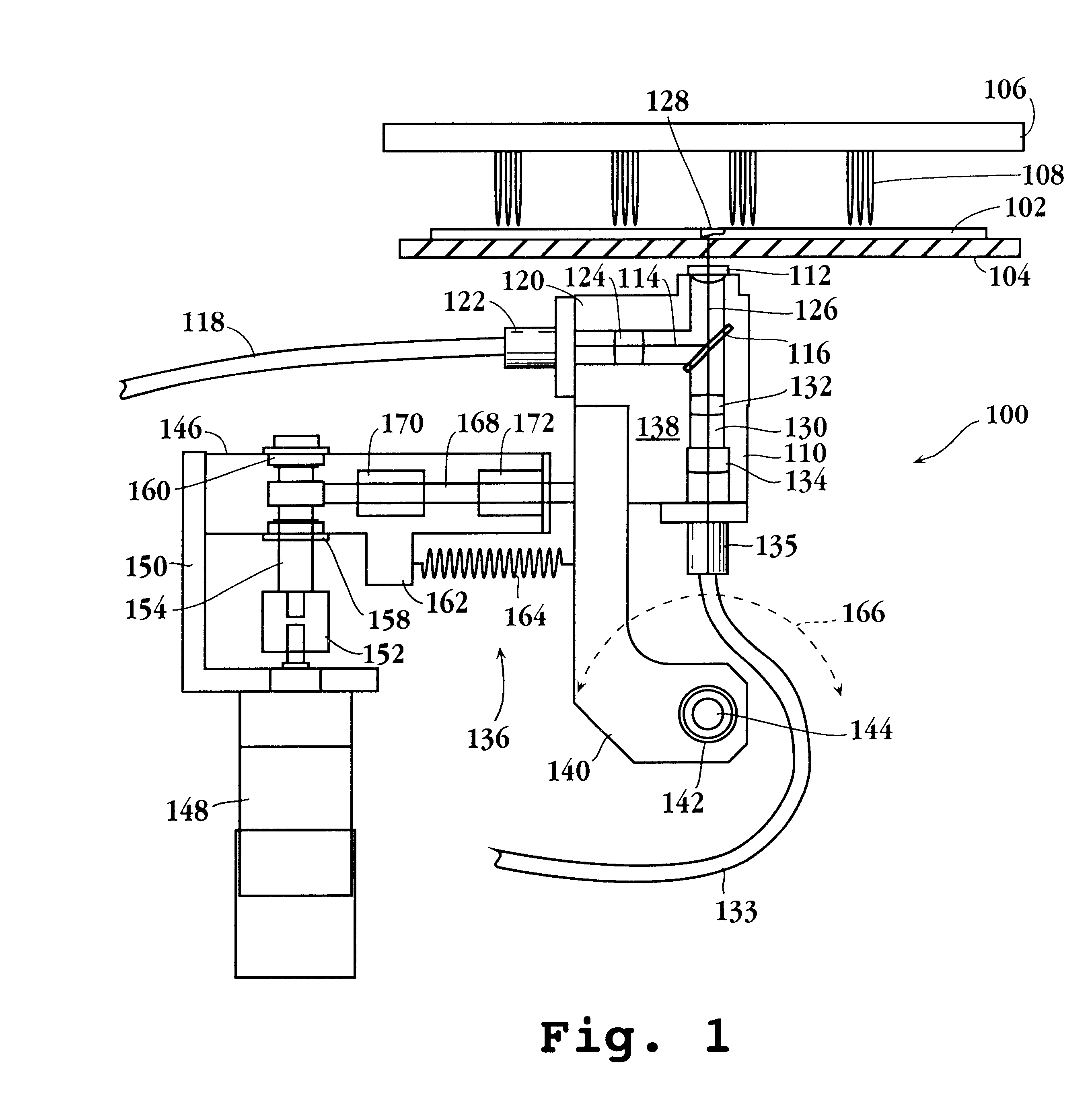
For further understanding of the invention, the drawings will now be considered. In FIG. 1 is depicted a detection station 100. In. conjunction with the detection station is a microfluidic chip 102, held in position by a quartz plate 104. The quartz plate may be part of a vacuum chuck, not shown, whereby the microfluidic chip 102 is held in fixed registry in relation to the detection station 100. Other ways of maintaining the microfluidic chip in place include gravity, force pins, pressure, clips, reversible adhesives, etc. Also depicted is an electrode lid 106 with electrodes 108, where the electrodes 108 can extend into ports of the microfluidic chip 102, during operation of electrokinetic processes. As described above, the. microfluidic chip 102 will have a plurality of channels, where the system for only one channel is shown. The detection station has optical housing 110, which is a small tubular housing, which may be made of any convenient material, e.g., plastic, aluminum, ste...


PUM


Abstract

An optical detection and orientation device is provided comprising housing having an excitation light source, an optical element for reflecting the excitation light to an aspherical lens and transmitting light emitted by a fluorophore excited by said excitation light, a focussing lens for focusing the emitted light onto the entry of an optical fiber, which serves as a confocal aperture, and means for accurately moving said housing over a small area in relation to a channel in a microfluidic device. The optical detection and orientation device finds use in identifying the center of the channel and detecting fluorophores in the channel during operations involving fluorescent signals.

Description

The field of this invention is fluorescent detection in microfluidic arrays.BackgroundThe combination of combinatorial chemistry, sequencing of the genomes of many species and relationships between genotype and physical and biological traits has greatly expanded the need to perform determinations of different events. The multiplicity of new compounds that can be prepared using various forms of combinatorial chemistry and the numerous targets involving wild-type and mutated genes, had extraordinarily increased the number of determinations of interest in developing compounds having biological activity. These compounds include drugs, biocides, pesticide resistance, disease organism resistance and the like. In addition, the interest in discriminating between different genomes, relating specific mutations to phenotypes, defining susceptibilities to various environmental effects in relation to single nucleotide polymorphisms, and identifying the genomes of organisms to provide better defe...

Claims


Application Information

Patent Timeline
IPC IPC(8): G01N21/64G01N37/00
CPCG01N21/6452G01N21/6458G01N21/6428G01N2021/6478G01N2201/101B01L3/5027B01L2200/14G01N2021/6439G01N2021/6419G01N2021/6421
Inventor MAHER, KEVINSMITH, TIMOTHY F.BJORNSON, TORLEIF OVE
Owner MONOGRAM BIOSCIENCES
Why Eureka
Try Eureka