Multispectral wide-field endoscopic imaging of fluorescence

a fluorescence imaging and multi-spectral technology, applied in the field of wide-field fluorescence imaging, can solve the problems of less than ideal prior methods and equipment for wide-field fluorescence imaging, less than ideal sensitivity and specificity for diagnosis of diseases of prior wide-field fluorescence imaging equipment, and less than ideal prior methods and equipment in one or more of many ways, so as to reduce one or more undesirable effects of interfering fluorescence signal, improve signal to background ratio, and reduce interferen

Active Publication Date: 2015-08-06
UNIV OF WASHINGTON
View PDF1 Cites 72 Cited by
  • Summary
  • Abstract
  • Description
  • Claims
  • Application Information

AI Technical Summary

Benefits of technology

[0008]Methods and apparatus as described herein provide improved imaging with co-registered fluorescence and reflectance signals. The reflectance signal co-registered with the fluorescence signal allows the fluorescence signal to be corrected in response to the reflectance signal. In many embodiments, one or more characteristics of an interfering background fluorescence can be used to decrease one or more undesirable effects of the interfering fluorescence signal on a fluorescence signal of interest in order to characterize and / or quantify the fluorescence signal of interest. The interfering fluorescence signal may be related to the reflectance signal, such that the reflectance signal can be used to decrease interference from the interfering fluorescence signal from the fluorescence signal of interest. The interfering fluorescence signal may comprise a fluorescence emission spectrum overlapping with the signal of interest. Correcting for the interfering fluorescence signal with the reflectance signal can provide an improved signal to background ratio and improved quantification of the fluorescence signal of interest.INCORPORATION BY REFERENCE

Problems solved by technology

Prior methods and apparatus for wide field fluorescence imaging can be less than ideal in at least some respects, and the prior methods and apparatus can be less than ideal in one or more of many ways.
The sensitivity and specificity for diagnosis of diseases of prior wide field fluorescence imaging apparatus can be less than ideal, for example.
Also, quantification of the amounts of fluorescence can be less than ideal.
Prior methods and apparatus that may be suited for use with imaging devices such as microscopes, which may be limited to a plane, can be less than ideally suited for use with wide field imaging in which the distance of the object can vary (e.g. within a cylindrical shaped body lumen), and field-of-view is limited in real time.
Also, the stability and repeatability of the measurement scans of the prior methods and apparatus can be less than ideal in at least some instances.
Determining the location and registration of prior fluorescence signals can be less than ideal in at least some instances.
For example, the fluorescence measurement may be combined with one or more imaging modalities, and the fluorescence measurement itself may not provide sufficient structure to register the fluorescence signal with images from other signals.
Prior methods and apparatus of wide field fluorescence imaging can be less than ideal suited to determine subtle variations of the desired measurement signal.
For example, prior methods and apparatus can be less than ideally suited to correct spectral overlap, in which a spectrum from one molecular labeling species overlaps with one or more other molecular labeling species.
Also, the prior methods and apparatus can be less than ideally suited to correct background fluorescence, which can at least partially obscure a desired measurement signal in at least some instances.
The prior methods and apparatus of wide field fluorescence imaging can be less than ideally suited to measure changes over time.
However, the prior methods and apparatus are less than ideally suited to repeatedly locate, identify, and measure changes in tissue over time for a specified location for an individual patient.

Method used


Image

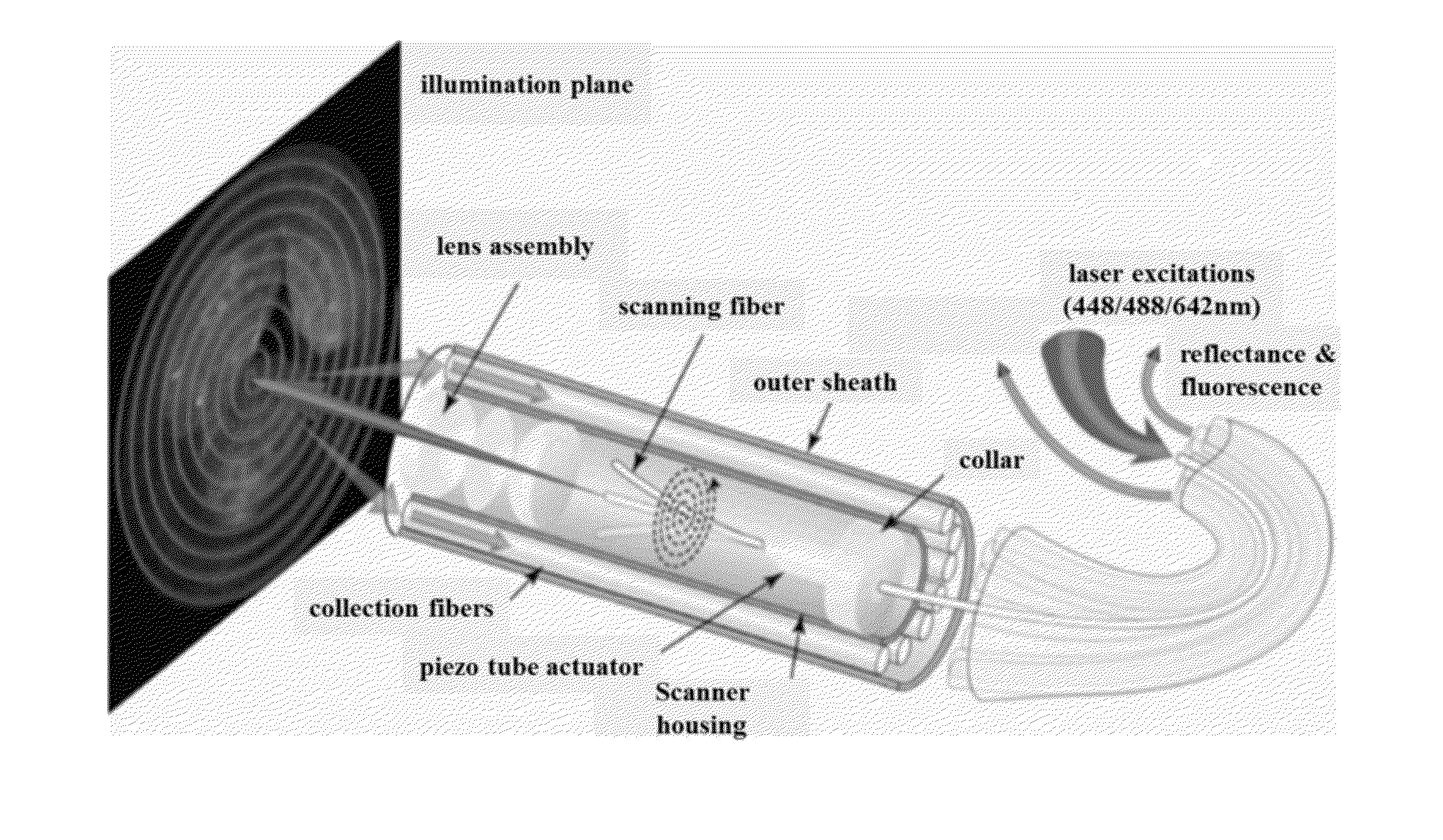
  • Multispectral wide-field endoscopic imaging of fluorescence
  • Multispectral wide-field endoscopic imaging of fluorescence
  • Multispectral wide-field endoscopic imaging of fluorescence

Examples


example 1

Detection Sensitivity of Scanning Fiber Endoscope with Multiple Fluorescence-Reflectance Imaging Channels for Guiding Biopsy

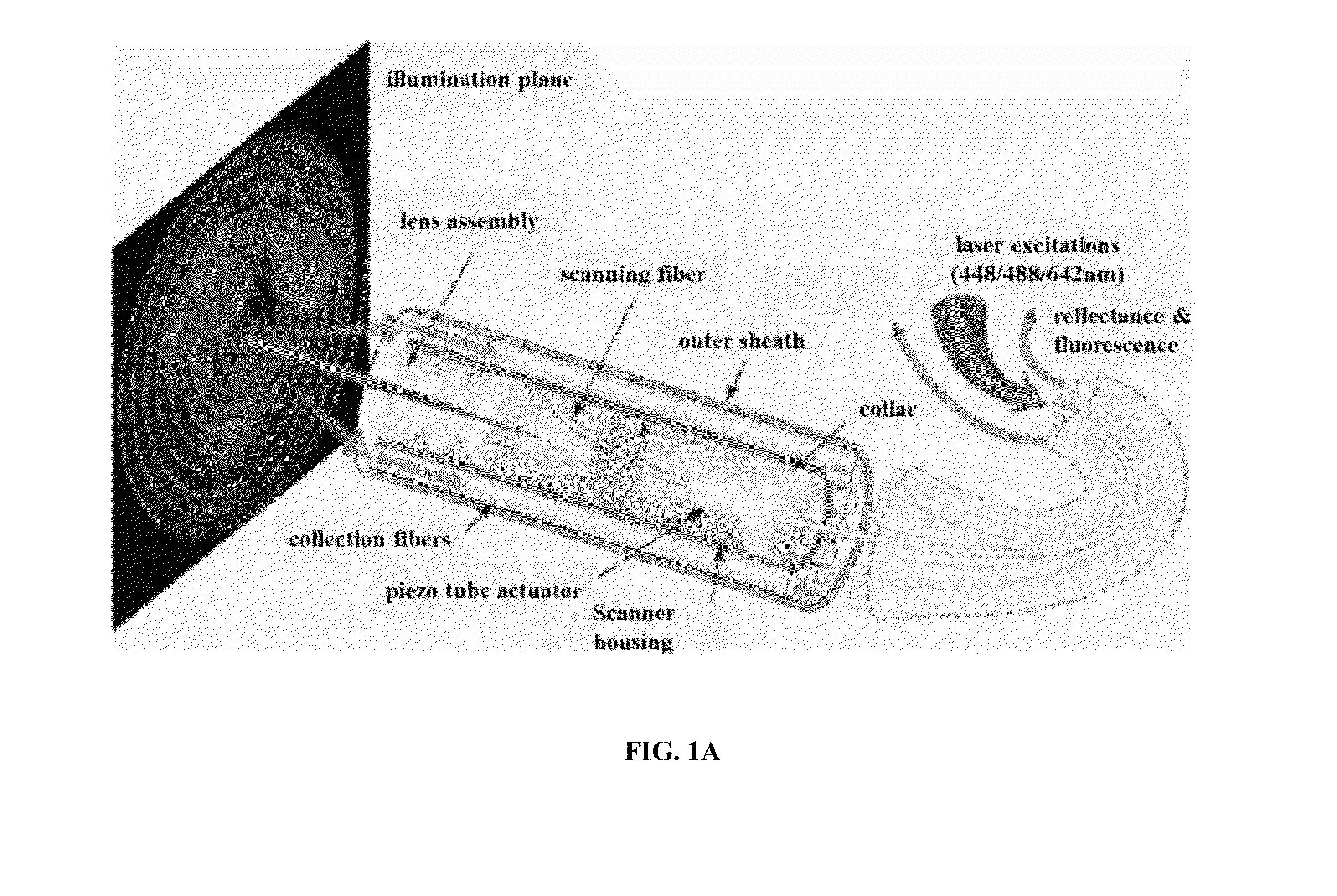
[0201]This example is related to the above section titled “Scanning Fiber Endoscope with multiple fluorescence-reflectance imaging channels for guiding biopsy.”

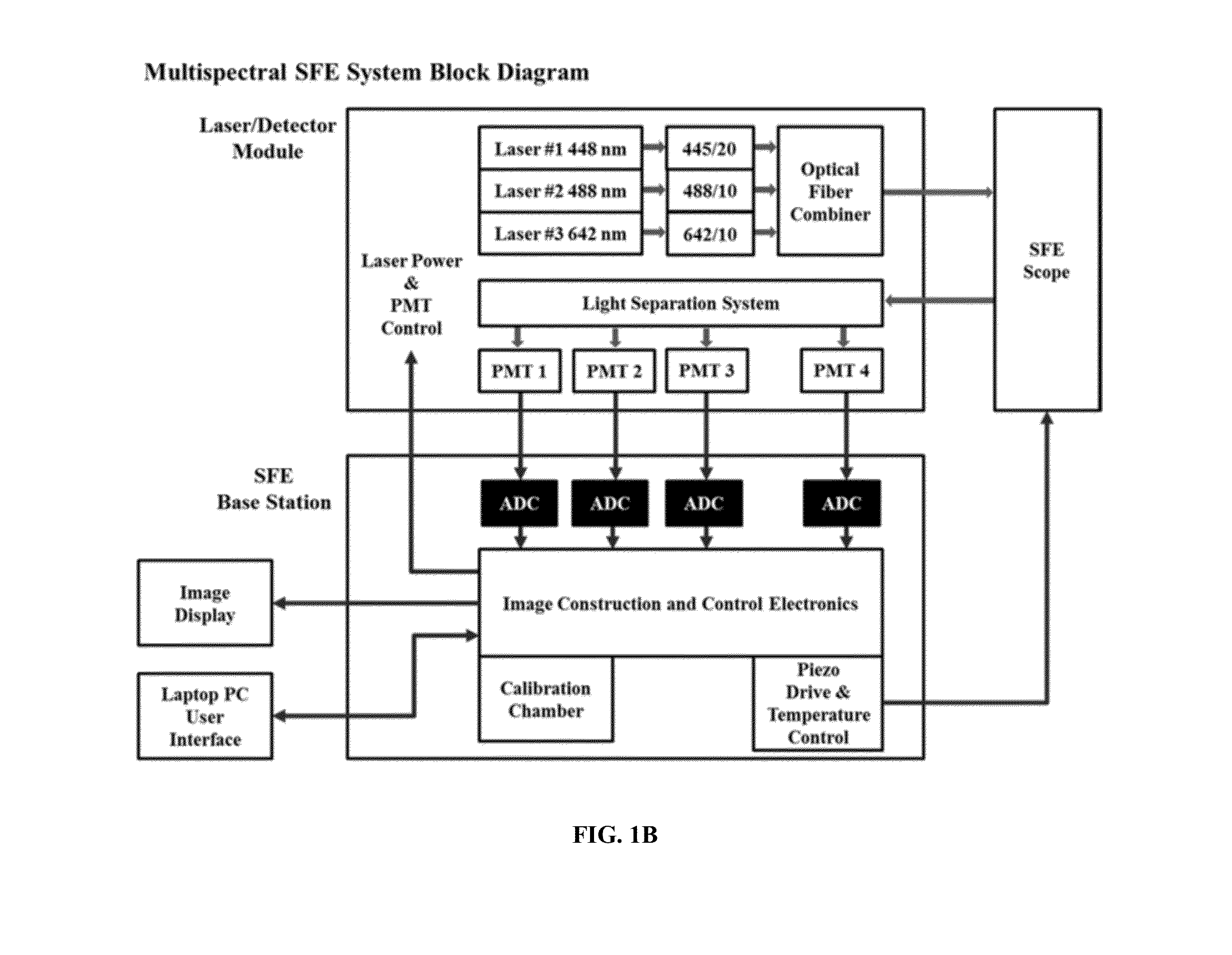
[0202]The detection sensitivity of the SFE was evaluated with a series of small-volume (50 uL) and low-concentration (nanomolar to micromolar) fluorophore dilutions. All experimentation used low laser output powers of each channel (2.2 mW 448 nm, 3.2 mW 488 nm, and 5 mW 642 nm) measured with Newport optical power meter (Model 1830-C). In the current study, the fluorescein and Cy5.5 dyes were chosen for the sensitivity test, since they were to be used in the next step ex vivo or in vitro image applications.

[0203]The multispectral SFE detection sensitivity limit was 5 nanomolar for the fluorescein dye and 10 nanomolar for the Cy5.5 dye at video rate with signal-noise-ratio (SNR) at 2:1. The SFE detection c...

example 2

Application of Multi-Spectral Scanning Fiber Endoscope with Concurrent Autofluorescence Mitigation for Enhanced Target-to-Background Ratio Imaging

[0208]This example is related to the above section titled “Multi-spectral Scanning Fiber Endoscope with concurrent autofluorescence mitigation for enhanced target-to-background ratio imaging.”

[0209]Validation of the AF Mitigation

[0210]As illustrated in FIG. 3A-D, it is assumed that the AF emission spectral profiles were nearly identical for the 445-nm excitations and the 488-nm excitations, so that a constant ratio can be applied to AF1 (in the AF channel) to calculate AF2 (in the detection channel).

[0211]To validate this assumption, we acquired the individual AF emission spectra of the two excitation wavelengths using a quantitative fluorescence imaging instrument—the IVIS Spectrum (Perkin-Elmer, Norwalk, Conn.). Ex-vivo porcine esophagus epithelium tissue was used in this validation study for the imaging. Porcine esophagus is often used ...

example 3

Application of Color-Matched and Fluorescence-Labeled Esophagus Phantom

[0222]This example is related to the above section titled “Color-matched and fluorescence-labeled esophagus phantom.”

[0223]We developed a stable, reproducible three-dimensional optical phantom for the evaluation of a wide-field endoscopic molecular imaging system. This phantom mimicked a human esophagus structure with flexibility to demonstrate body movements. At the same time, realistic visual appearance and diffuse spectral reflectance properties of the tissue were simulated by a color matching methodology. A photostable dye-in-polymer technology was applied to represent biomarker probed “hot-spot” locations. Furthermore, fluorescent target quantification of the phantom was demonstrated using a 1.2 mm ultrathin scanning fiber endoscope with concurrent fluorescence-reflectance imaging.

[0224]Color Matching and Diffuse Reflectance

[0225]Initially paint recipes were formulated wherein constituent paint ratios were a...


PUM

PropertyMeasurementUnit
cross-sectional distanceaaaaaaaaaa
timeaaaaaaaaaa
timeaaaaaaaaaa

Abstract

Improved methods, systems and apparatus relating to wide field fluorescence and reflectance imaging are provided, including improved methods, systems and apparatus relating to removal of background signals such as autofluorescence and / or fluorophore emission cross-talk; distance compensation of fluorescent signals; and co-registration of multiple signals emitted from three dimensional tissues.

Description

CROSS-REFERENCE[0001]This application claims the benefit of U.S. Provisional Application No. 61 / 934,479, filed Jan. 31, 2014, which application is incorporated herein by reference.STATEMENT AS TO FEDERALLY SPONSORED RESEARCH[0002]This invention was made with the support of the United States government under Contract number U54CA163059 by the National Institutes of Health (NCI).BACKGROUND OF THE INVENTION[0003]Prior methods and apparatus for wide field fluorescence imaging can be less than ideal in at least some respects, and the prior methods and apparatus can be less than ideal in one or more of many ways. The sensitivity and specificity for diagnosis of diseases of prior wide field fluorescence imaging apparatus can be less than ideal, for example. Also, quantification of the amounts of fluorescence can be less than ideal. Wide field imaging with a small device such as an endoscope can include imaging tissue structures of objects at varying distances from the object. The varying d...

Claims


Application Information

Patent Timeline
Patent Type & Authority Applications(United States)
IPC IPC(8): A61B1/04G01N21/64A61B1/00G02B23/26
CPCA61B1/043G02B23/26G01N21/6456G01N2201/08A61B1/00165A61B1/00172G01N2201/12A61B1/00009G01N21/278G01N21/474G01N21/6486G01N2021/4742G01N2021/6417G01N2021/6419G01N2021/6484G01J3/0278G01J3/06G01J3/10G01J3/28G01J3/36G01J3/4406G01J2003/065G01J3/0208G01J3/0218G02B26/103A61B1/000094
Inventor YANG, CHENYINGSEIBEL, ERIC J.NELSON, LEONARD Y.SOPER, TIMOTHY D.
Owner UNIV OF WASHINGTON
Why Eureka
Try Eureka