Air damper
a damper and air technology, applied in the direction of machine supports, shock absorbers, washing machines, etc., can solve the problems of difficult to reduce in size and weight, difficult to absorb vibration, and the structure of the equipment body cannot be simplified, so as to reduce the size and weight
- Summary
- Abstract
- Description
- Claims
- Application Information
AI Technical Summary
Benefits of technology
Problems solved by technology
Method used
Image
Examples
first embodiment
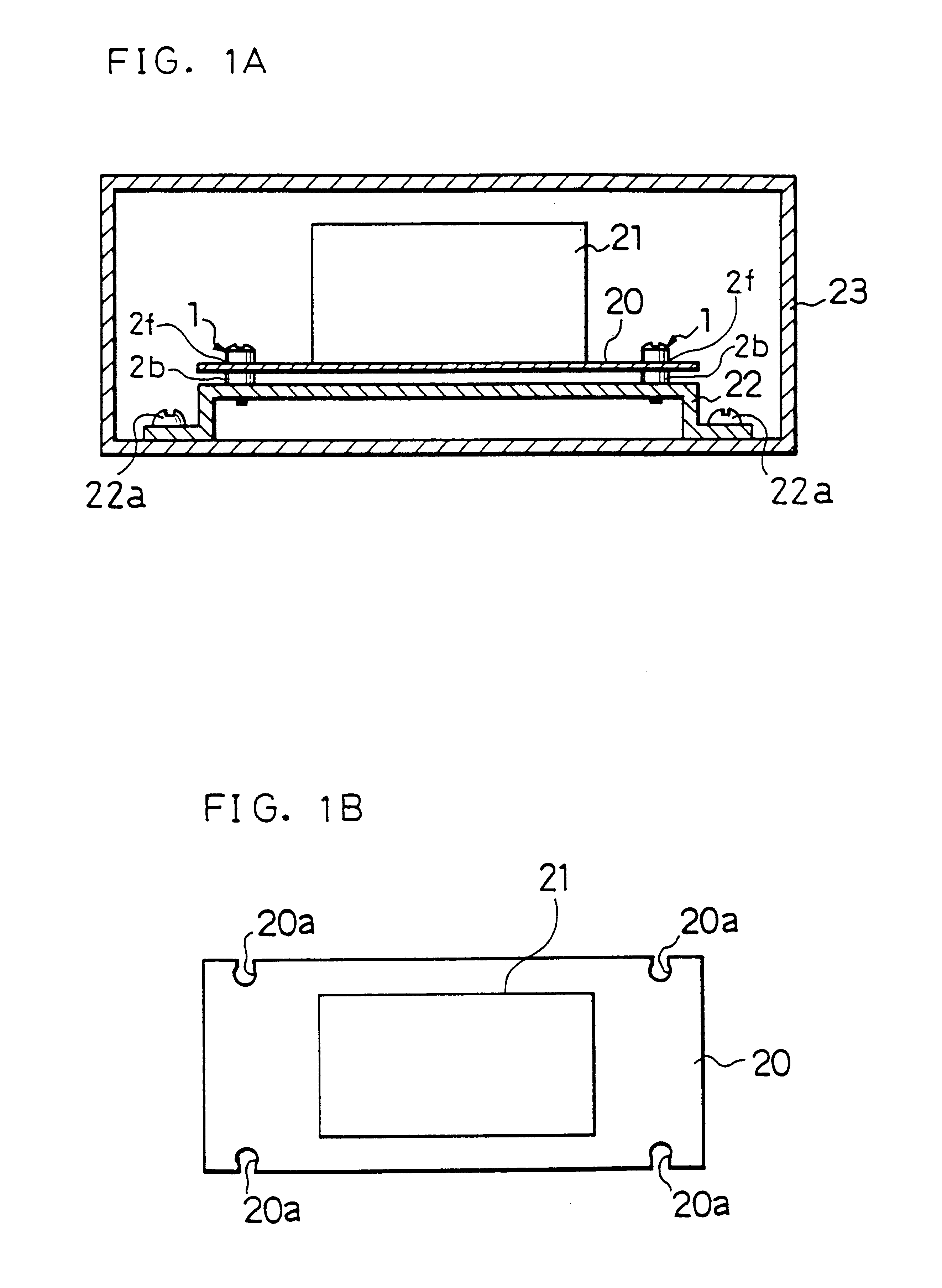
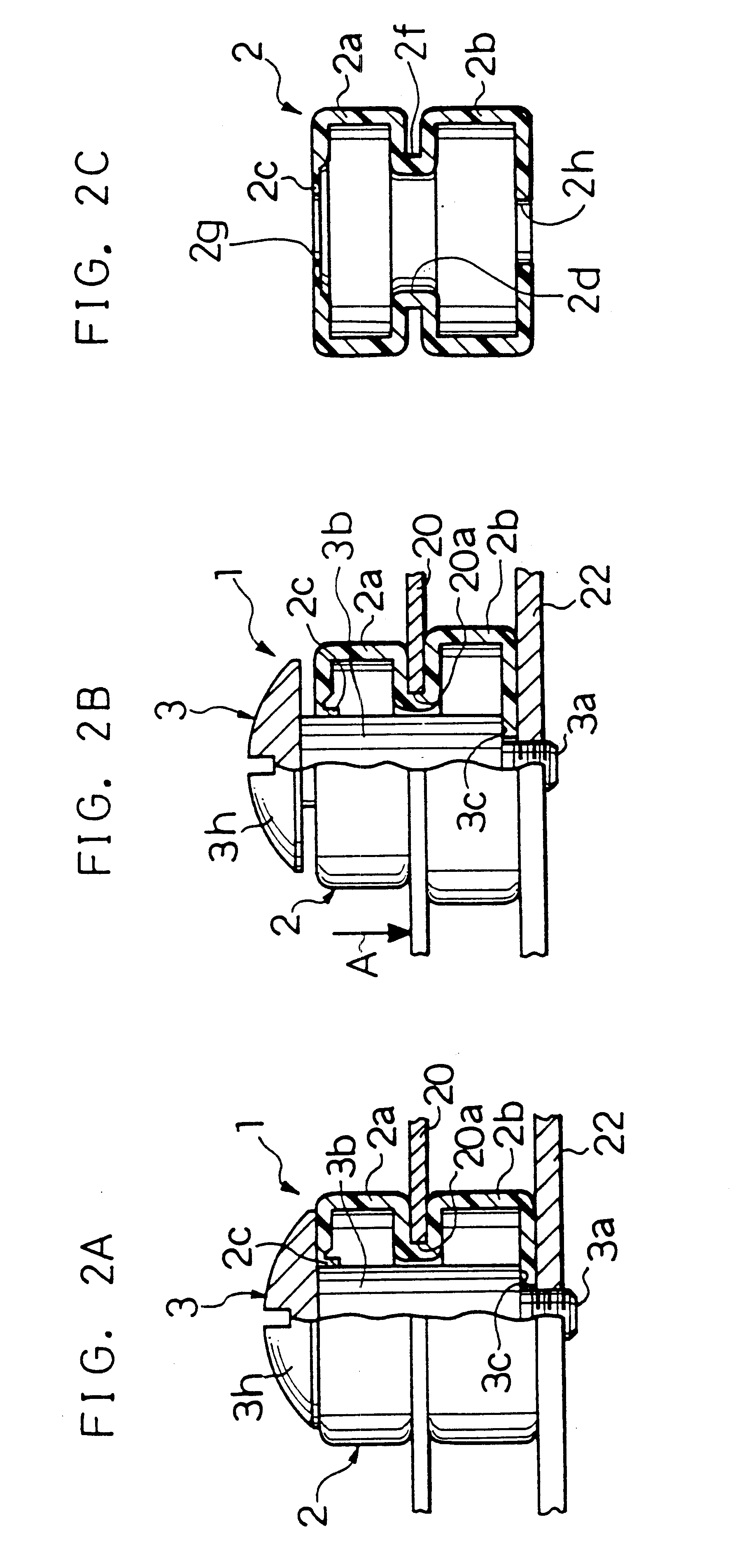
FIG. 1A is a cross-sectional elevation view of an example of a body of equipment 23 using air dampers 1 in the present invention. FIG. 1B is a plan view of a support board 20 shown in FIG. 1A. FIG. 2A is a side view, partly in cross-section, of the air damper 1. FIG. 2B is a side view, partly in cross-section, showing the state that the support board 20 mounted on the air damper 1 is depressed in the direction shown by an arrow A. FIG. 2C is a cross-sectional side view of a casing 2 of the air damper 1. The casing 2 includes cylindrical members 2a and 2b which are stacked in a manner of one above the other.
As shown in FIG. 1A, in the body of equipment 23, a precision electronic and mechanical component 21 to be supported is mounted on the support board 20. The support board 20 is mounted on intermediate sections 2f of four air dampers 1, and connected to a frame 22 through respective cylindrical members 2b. The support board 20, the frame 22 and the body of equipment 23 are preferab...
second embodiment
FIG. 3A is a side view, partly in cross-section, of an air damper 4 of a second embodiment in the present invention. FIG. 3B is a side view, partly in cross-section, showing the state that the support board 20 mounted on the air damper 4 is depressed in the direction of an arrow A. FIG. 3C is a cross-sectional side view of a casing 5 of the air camper 4. The air damper 4 includes bellows 5a capable of expanding and contracting in the axial direction, as replacement for the cylindrical member 2a of the air damper 1 in the first embodiment. The other configurations are the same as those of the first embodiment.
As shown in FIG. 3A to FIG. 3C, a cylindrical member 5b is disposed at the lower stage of the bellows 5a. The bellows 5a includes a thin walled portion 5c closely contacting the shank 3b of the shoulder bolt 3, in a manner similar to that of the first embodiment.
In the air damper 4 of this embodiment, when the casing 5 is mounted on the frame 22 in a manner that the casing 5 is ...
third embodiment
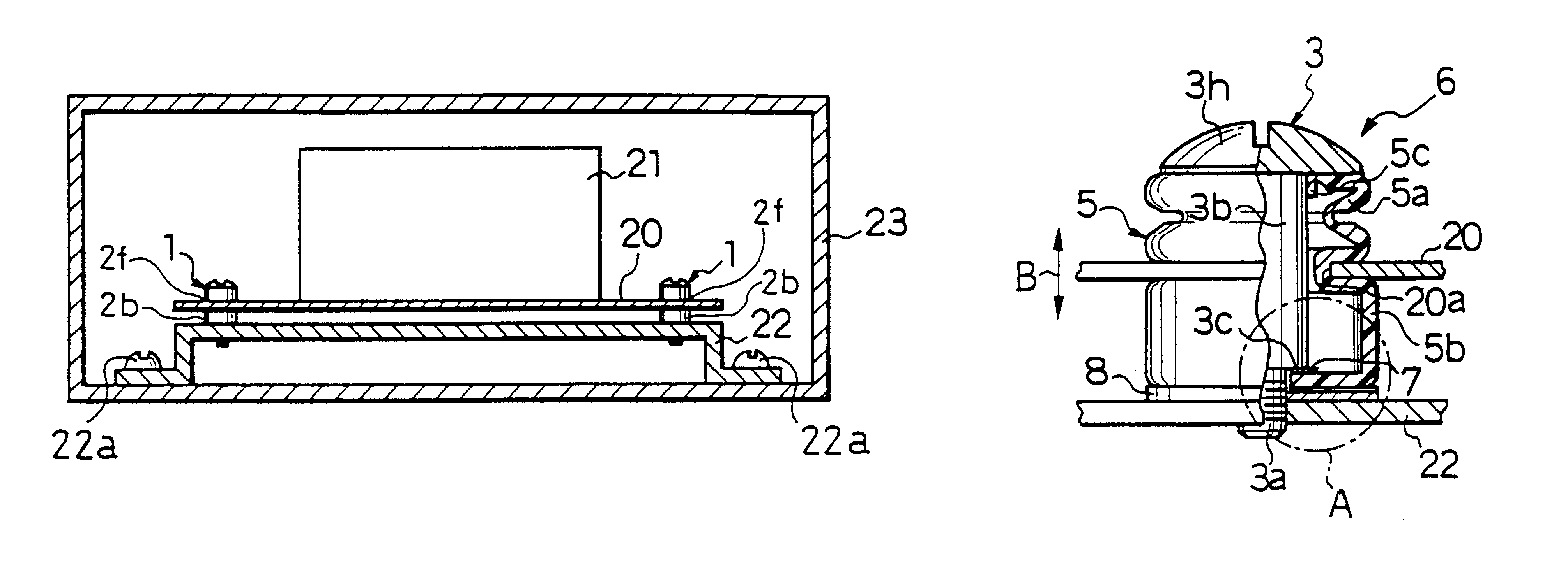
FIG. 4A is a side view, partly in cross-section, of an air damper 6 of a third embodiment in the present invention. FIG. 4B is an enlarged cross-sectional side view of the region encircled by a chain line A in FIG. 4A. The air damper 6 of the third embodiment includes an air passage (hereinafter is referred to as orifice) to communicate between the interior and the outside of the casing 5 as described bellow in detail. The other configurations are similar to those of the second embodiment.
In the third embodiment, the casing 5 is configured in a manner that when the support board 20 moves as shown by an arrow B due to extraneous vibration, the capacity of the casing 5 increases or decreases corresponding to a moving direction of the support board 20. In other words, the bellows 5a and the cylindrical member 5b of the casing 5 are configured in a manner that the capacity change of the bellows 5a by a predetermined distance of movement of the support board 20 in a direction of the arro...
PUM
| Property | Measurement | Unit |
|---|---|---|
| outer diameters | aaaaa | aaaaa |
| outer diameter | aaaaa | aaaaa |
| thickness | aaaaa | aaaaa |
Abstract
Description
Claims
Application Information
 - R&D
- Intellectual Property
- Life Sciences
- Materials
- Tech Scout
- Unparalleled Data Quality
- Higher Quality Content
- 60% Fewer Hallucinations
Browse by: Latest US Patents, China's latest patents, Technical Efficacy Thesaurus, Application Domain, Technology Topic, Popular Technical Reports.
© 2025 PatSnap. All rights reserved.Legal|Privacy policy|Modern Slavery Act Transparency Statement|Sitemap|About US| Contact US: help@patsnap.com


