Angled opto-mechanical device

Inactive Publication Date: 2002-06-11
TELEFON AB LM ERICSSON (PUBL)
View PDF11 Cites 45 Cited by
  • Summary
  • Abstract
  • Description
  • Claims
  • Application Information

AI Technical Summary

Benefits of technology

The second side of the fixture can be covered by plastic which makes any necessary polishing easier. By using suitable shaped opposing means (e.g. with bevellings) in the mould cavity which give an impression with markings, the distance to the second side of the fixture can be more easily matched during polishing.
One advantage of the present invention is that the connector can be quickly and easily connected and has high mechanical precision. It is furthermore simple and cheap to manufacture.
Another advantage of the present invention is that the precision requirements on the mould cavity are considerably reduced when micromechanical supporting elements are used. The manufacturing i

Problems solved by technology

The bending module is, however, not intended

Method used


Image

  • Angled opto-mechanical device
  • Angled opto-mechanical device
  • Angled opto-mechanical device

Examples


Embodiment Construction

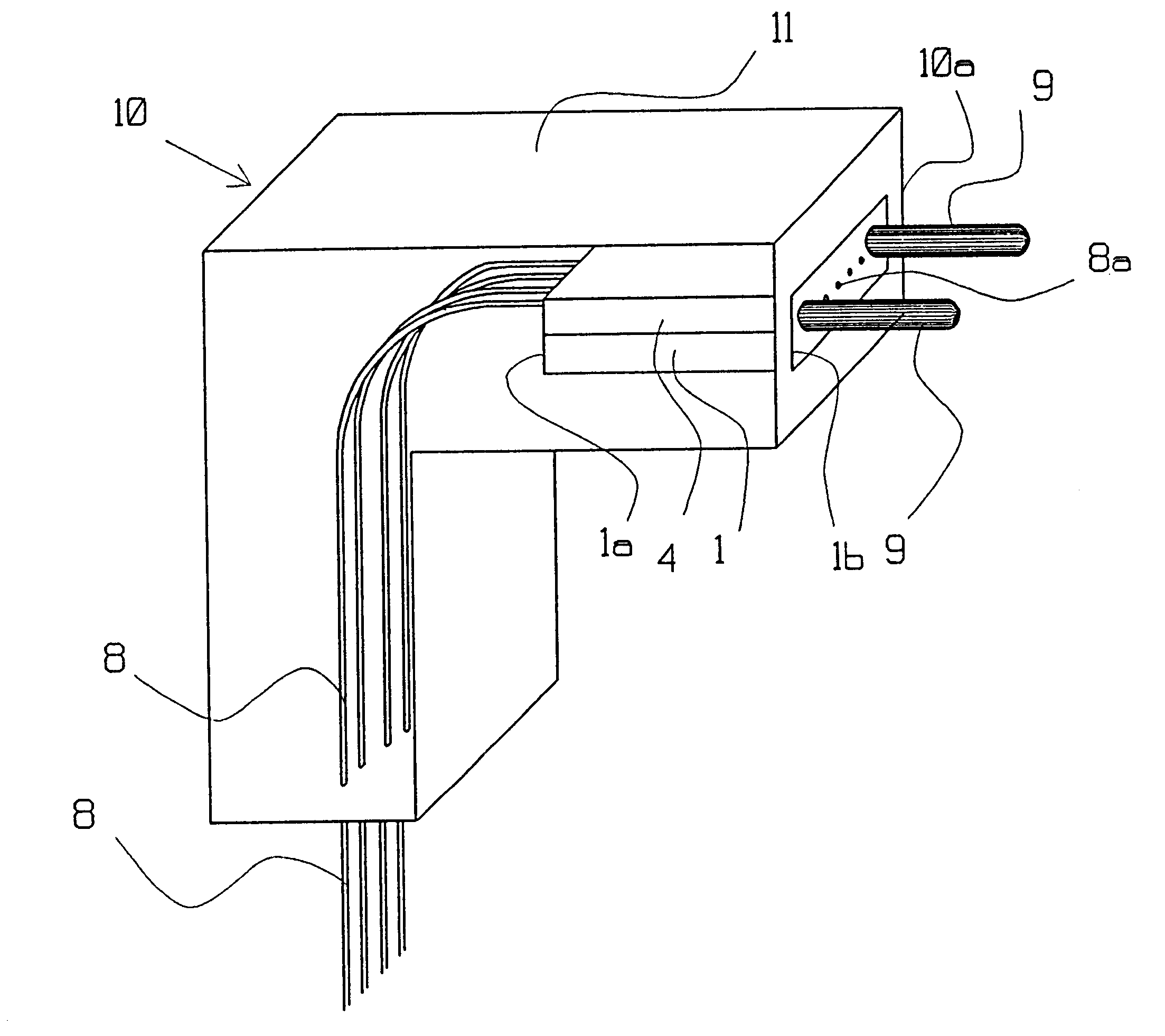
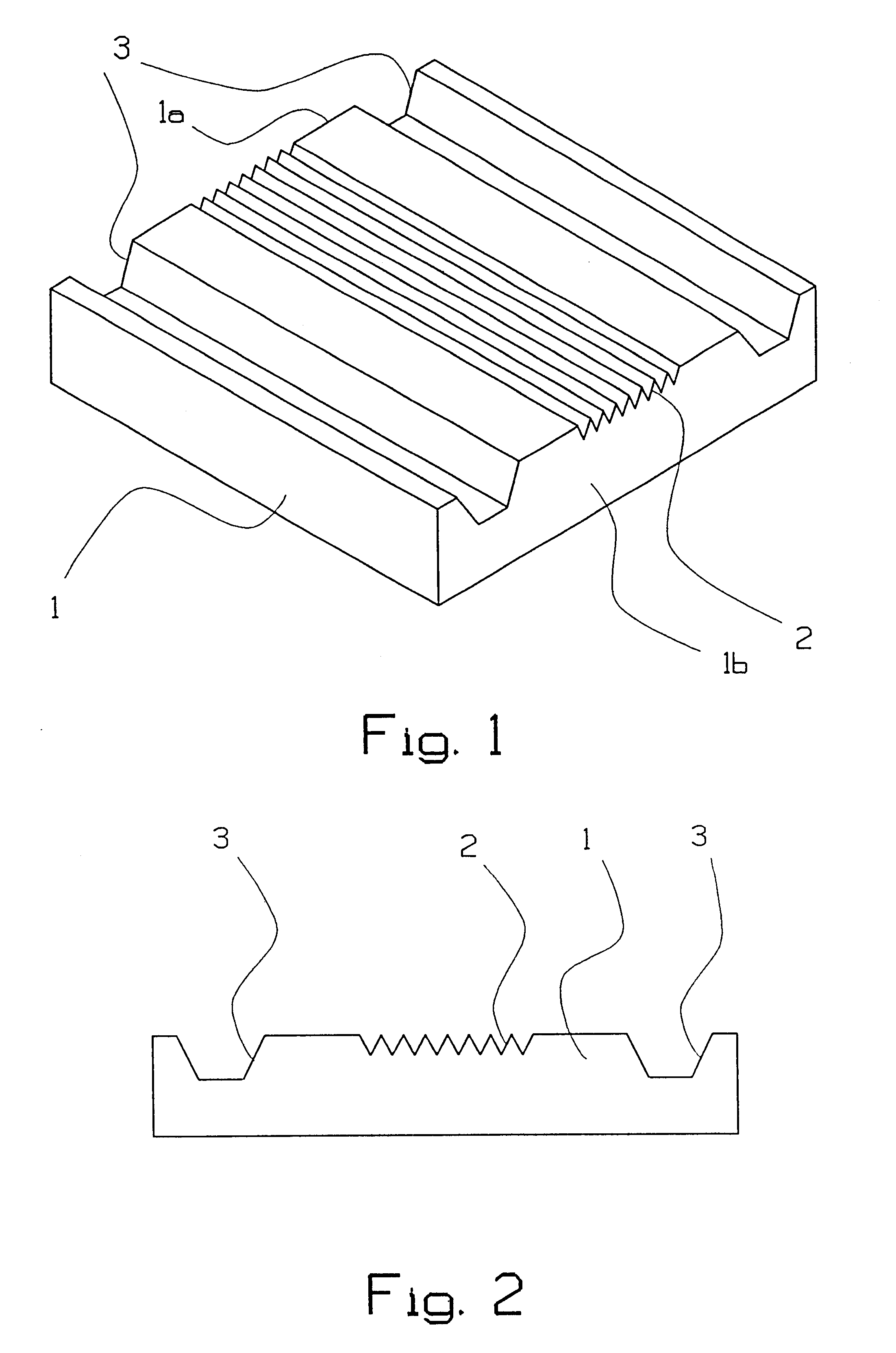
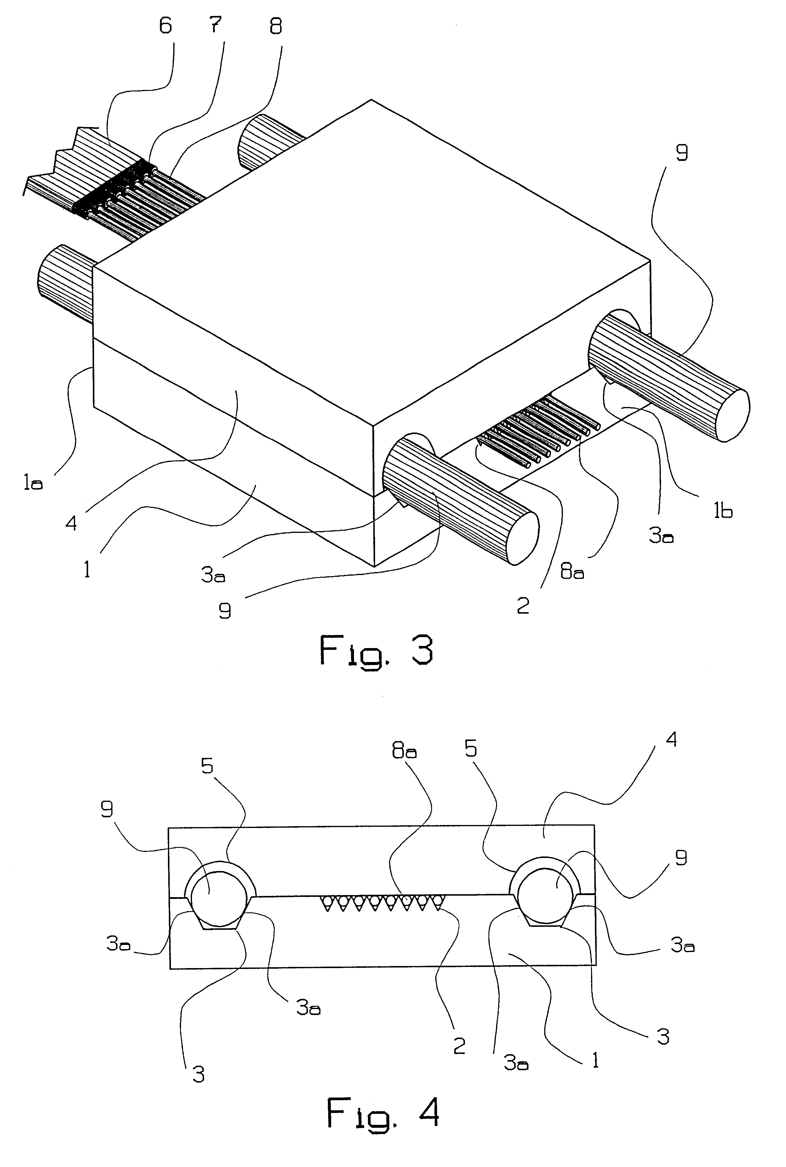
FIGS. 1 and 2 show in perspective and from one side a high-precision part or fixture 1, preferably made of silicon. The fixture 1 has grooves 2 for optical fibres from e.g. a fibre ribbon cable. The number of grooves 2 in FIGS. 1 and 2 are eight but can be any arbitrary number. The fixture 1 has also grooves 3 for guide pins (which are used for the external mechanical connection. The grooves 2, 3 can have any arbitrary shape in cross-section but have preferably a V-shape. The grooves 3 advantageously have flat bottoms. In the following they will be referred to as V-grooves. All the V-grooves are straight and parallel and run on the upper side of the fixture from a first fixture side la to a second fixture side 1b.

Preferably several fixtures 1 are manufactured together on a silicon disc. All the V-grooves 2, 3 are defined by one and the same mask, after which wet etching takes place. The precision between the V-grooves 2, 3 is thereby ensured.

Above the fixture 1 is, according to the ...


PUM


Abstract

The present invention relates to an angled opto-mechanical connector (10) and to a manufacturing process for the same. The connector (10) comprises a fixture (1) with straight and parallel grooves (2, 3) of two sizes running on the upper side of the fixture (1) from a first fixture side (1a) to a second fixture side (1b). A lid (4) is fastened above the fixture (1). Fibre ends (8a) of optical fibres (8) are placed in the capillaries which are formed between the smaller grooves (2) of the fixture and the lid (4) in such a way that they stick out through the side of the fixture (1b). A plastic capsule (11) encloses the fixture (1), the lid (4) and the fibres (8) completely or partially. The fibres (8) stick out from the plastic capsule (11) in a direction separated from that defined by the grooves of the fixture. The connector (10) can also have an opto-mechanical interface of the above mentioned type at its other end (10b).

Description

The present invention relates to an angled opto-mechanical connector and to a production method for the same.STATE OF THE ARTIn order to reduce the total cost for connecting optical fibres, multifibre contacts are used. The advantage of these are that the time-demanding and thereby expensive mounting and subsequent working stages can be performed on several fibres at the same time. Several embodiments of multifibre connectors are known.One of these is the Japanese so-called MT-connector. It is based on a precision part made of extruded thermoplastic in which the fibres are mounted (glued).In another embodiment of multifibre connectors, an MT-compatible optical connector is directly extruded onto the fibres, see Swedish Patent Application 9301858-8. The fibres and guide pins are placed and fixed in V-grooves in the mould cavity itself after which the extrusion takes place. The method means that the gluing step disappears which rationalizes the production and is expected to lower its ...

Claims


Application Information

Patent Timeline
IPC IPC(8): G02B6/38G02B6/40
CPCG02B6/3829G02B6/3885G02B6/3865G02B6/3839G02B6/38
Inventor STEIJER, ODDMOLL, CHRISTERLINDSTROM, BENGTVIEIDER, CHRISTIANERIKSEN, PAULENGSTRAND, JAN-.ANG.KELARSSON, OLLEELDERSTIG, H.ANG.KAN
Owner TELEFON AB LM ERICSSON (PUBL)
Why Eureka
Try Eureka