Extruded profile filter framing

a profile filter and filter body technology, applied in the field of extruded profile filters, can solve the problems of complicated manufacturing of framed filters, non-airtight seals around framed filters, and difficult automation production processes to implement framed filters

Inactive Publication Date: 2002-06-18
3M INNOVATIVE PROPERTIES CO
View PDF21 Cites 91 Cited by
  • Summary
  • Abstract
  • Description
  • Claims
  • Application Information

AI Technical Summary

Problems solved by technology

This however, would likely result in a non-airtight seal allowing bypass around the framed filter.
This type of approach permits more flexibility in terms of frame forms and functionality than unitary filter frames, however, it generally results in framed filters which are complicated to manufacture while often not providing an airtight seal around the filter media.
This type of framed filter would be very difficult to implement in an automated production process due to the strategic placement of the adhesive within an enclosed space and the need for rapid assembly of three three-dimension pieces coming together simultaneously with very close tolerances.
Again, this is a complicated structure requiring multiple assembly steps.
This approach generally is only suitable for use in holding a flat filter media taunt along the peripheral edge of the rigid frame similar to a window screen.
Although the individual injection molded pieces can be suitable for continuous production processes, the frame assembly with the filter element is complicated such that it would generally require hand assembly.
Although this frame allows a filter to be formed from a sheet of flat material, the complex three-dimensional folding along three separate axis makes this an inherently complicated assembly to manufacture in a continuous process not to mention the need for subsequent adhesive application of a sealing strip.

Method used


Image

  • Extruded profile filter framing
  • Extruded profile filter framing
  • Extruded profile filter framing

Examples


Embodiment Construction

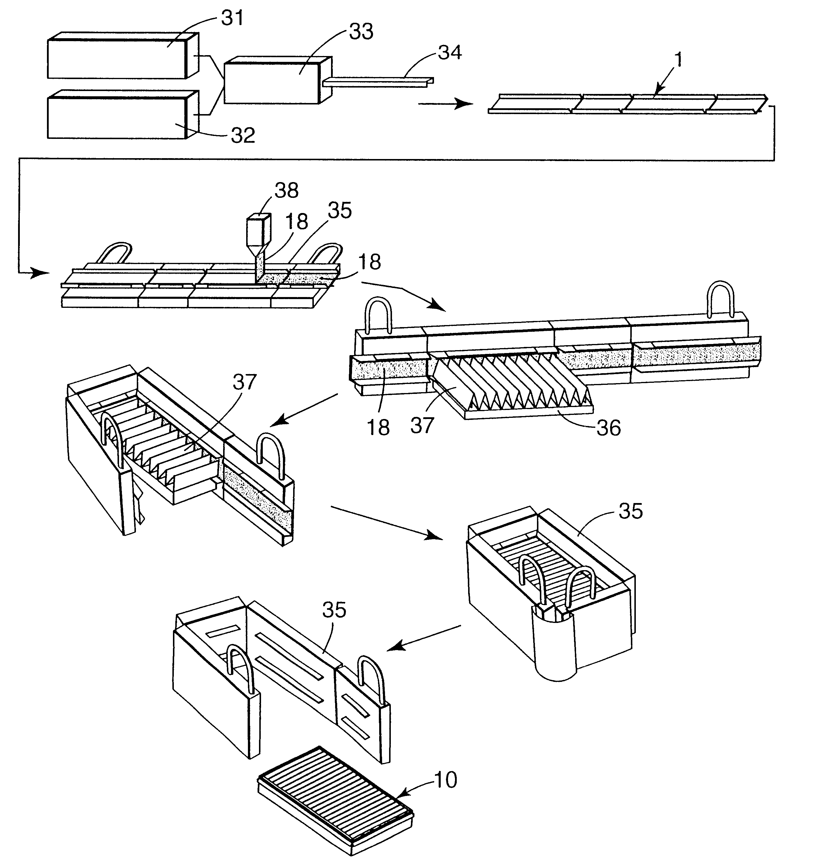
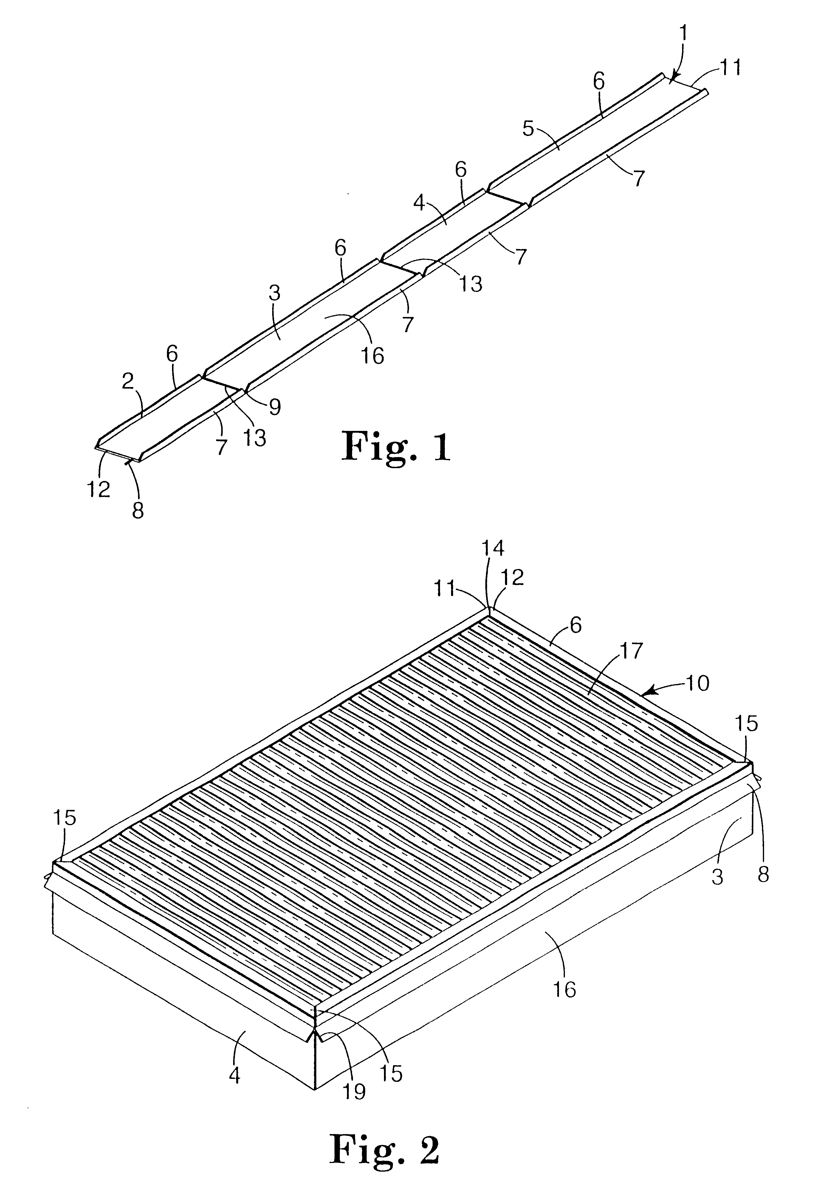
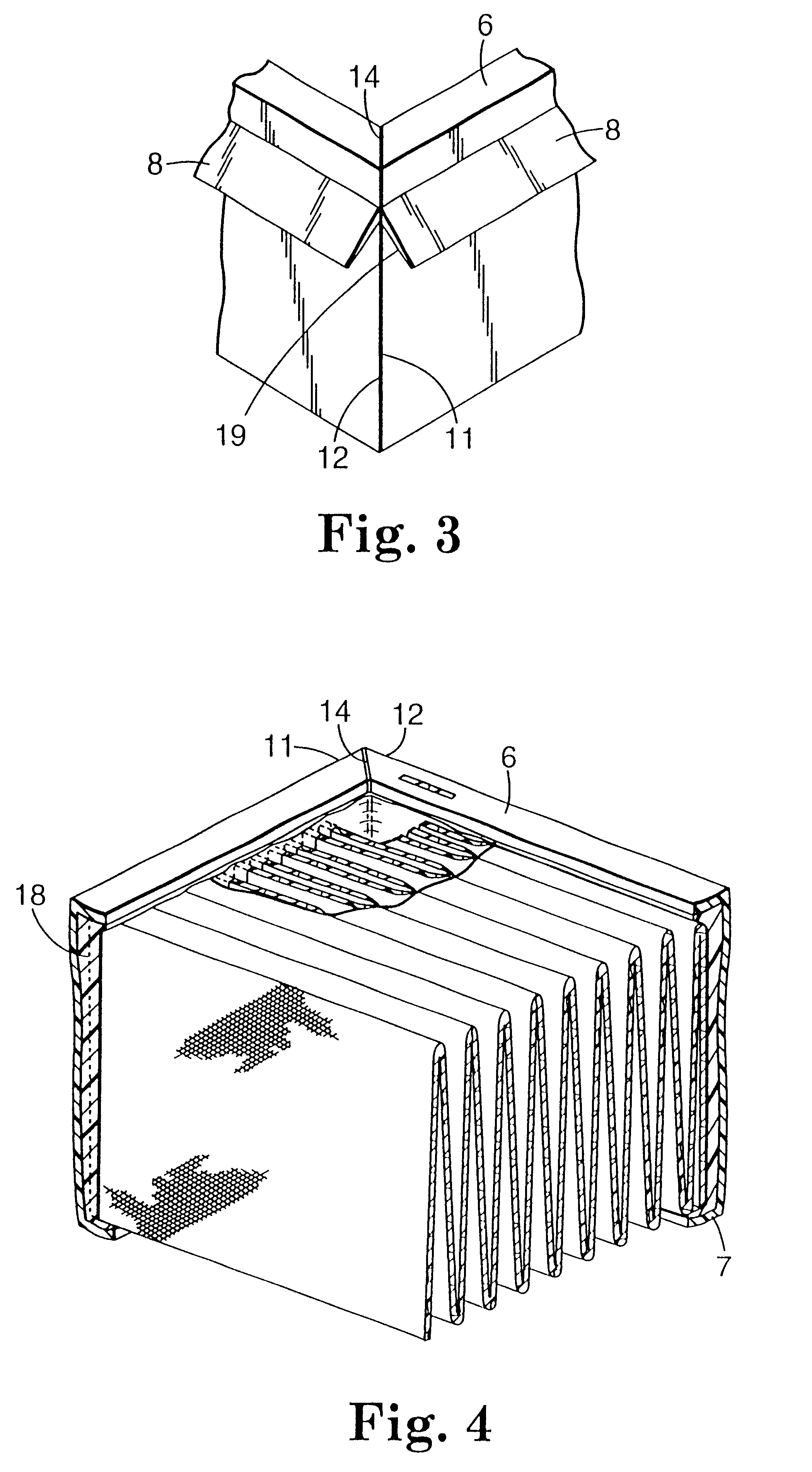
Two extruders were connected to a feed block / coextrusion die assembly capable of producing a continuous strip frame material, including a sealing lip, having a profile similar to that illustrated in FIG. 2. Sidewall and retaining tab segments of the strip frame material were 0.75-1.00 mm thick, the sidewall portion of the strip frame material was 32 mm wide, the filter retaining tabs were 5 mm wide, and the sealing lip was 6 mm long and had a tapered profile ranging from 1.5 mm at its juncture with the sidewall to 0.5 mm at its tip. The sidewall and filter retaining tab portions of the strip frame were formed from Polyfort.TM., a talc filled polypropylene resin (20% by weight talc) available from A. Schulman Inc. which was delivered to the feedblock / die assembly as a molten stream at a temperature of 205.degree. C. from the first extruder. The integral sealing lip portion of the strip frame material was formed from Santoprene.TM., available from Ashland Chemical Co., which was deliv...


PUM

PropertyMeasurementUnit
notch angleaaaaaaaaaa
notch anglesaaaaaaaaaa
heightaaaaaaaaaa

Abstract

A framed filter media comprising a filter media having a fluid inlet face and a fluid outlet face with peripheral sidewalls. The peripheral sidewalls are attached to a strip frame by an adhesive-potting compound. The continuous strip frame is formed into three or more (up to an infinite number if the sidewall sections(s) is formed into a circular filter frame) sidewall sections having a substantially flat sidewall and at least two projecting filter retaining tabs which form a channel on a first face of the sidewall section for containing the adhesive potting compound. The sidewall sections are separated by corner notches extending through the retaining tabs at least to the substantially flat sidewalls. Two terminal sidewall sections meet to form a seam such that the sidewall sections circumscribe the filter media peripheral sidewalls. The continuous strip frame is formed by extruding a continuous strip frame blank comprising at least a substantially flat sidewall and at least two projecting filter retaining tabs forming a continuous channel on a first face of the continuous strip frame blank. The filter retaining tabs are then notched to form corner notches which corner notches extend at least to the substantially flat sidewalls creating sidewall section between the corner notches and optionally scoring first and/or second faces of the sidewall portions to form living hinges. The continuous strip frame blank is further cut into discrete strip frame blanks.

Description

BACKGROUND AND FIELD OF THE INVENTIONThis invention is directed at a unitary filter frame capable of being formed by a continuous extrusion process.Conventionally three dimensional filter frames are formed by injection molding or similar type processes. In its simplest variation, the frame is directly formed as a unitary structure. A simple technique for this is described in U.S. Pat. No. 2,032,262 where a pleated filter is held in a jig with only the edge portions extending out of the jig. This jig is then inserted into a mold form and a plastic type material is injected, embedding the exposed pleat edges in the space between the jig and the mold form. Similarly, U.S. Pat. No. 5,792,229 shows an elastomeric filter frame formed directly on a pleated filter media by injection molding a foaming resin into the pleats of the pleated filter along the periphery of the pleated filter in one embodiment of the invention described. This filter requires a separate rigid frame in which the filt...

Claims


Application Information

Patent Timeline
Patent Type & Authority Patents(United States)
IPC IPC(8): B01D46/10B01D46/52B01D39/00B01D39/16B01D46/00
CPCB01D46/0001B01D46/0002B01D46/521B01D46/0016Y10T156/1028B01D2271/02B01D46/10
Inventor DUFFY, DEAN
Owner 3M INNOVATIVE PROPERTIES CO
Why Eureka
Try Eureka