
Endoscope with objective lens drive mechanism

a drive mechanism and endoscope technology, applied in the field of endoscopes for medical use, can solve the problems of affecting the quality of picture images, affecting the rotation speed of the endoscope, and the wire easily getting twisted,

Inactive Publication Date: 2002-06-25
FUJI PHOTO OPTICAL CO LTD
View PDF7 Cites 47 Cited by
  • Summary
  • Abstract
  • Description
  • Claims
  • Application Information

AI Technical Summary

Benefits of technology

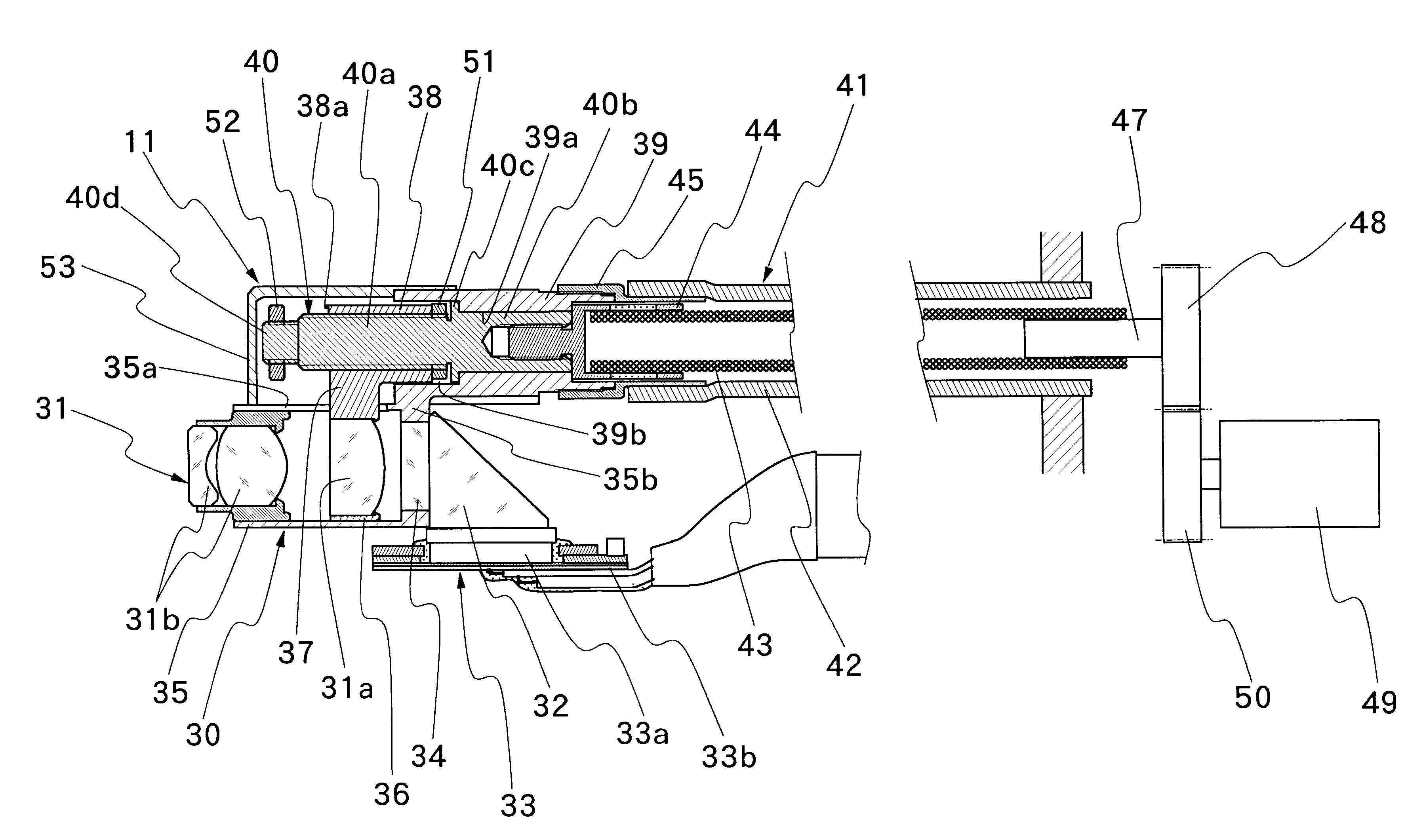
It is another object of the present invention to provide an endoscope with an objective lens drive mechanism which can transmit driving force securely to a movable lens of an objective lens system in reciprocating the movable lens accurately between predetermined positions and which can be operated constantly in stable conditions.
It is still another and more particular object of the present invention to provide an endoscope with an objective lens drive mechanism which can drive a movable lens of an objective lens system accurately relative to a fixed lens of an objective in alignment with optical axis at least to and from a fore position on the side of a subject and a rear position on the side of an imaging plane.
The nut portion is provided at an outer distal end of an arm portion which is connected to and extended out from the movable lens frame, and has a thickness which is substantially same as axial length of the movable lens frame. Preferably, the arm portion is fitted in and extended through an axial slot which is provided in the fixed lens frame, and thereby blocked against rotational movements relative to the fixed lens frame to preclude the possibilities of positional deviations of the movable lens relative to the fixed lens in the rotational direction. In this connection, the nut portion is preferably provided with an axial extension toward a proximal side of the arm portion thereby to increase a length of threaded engagement with said screw rod. In this case, the bearing member on the side of the fixed lens frame is provided with an open receptacle portion of a diameter larger than outside diameter of the nut portion to receive the axial extension of said nut portion therein.

Problems solved by technology

This is so especially when a movable lens is located in a fore position on the side of a subject because the focal depth is shallow in the fore position and therefore a slight deviation from a predetermined position will invite considerable deteriorations in quality of picture images.
The control cable of this type has another problem that, after repeated operations, the operating wire can get elongated to cause variations in pulling stroke length.
On the other hand, the rotating type control cable also has inherent drawbacks that its wire easily gets twisted and fails to transmit rotation smoothly to its fore end, and, gets elongated after repeated use similarly to the above-mentioned push-pull type.

Method used


Image

  • Endoscope with objective lens drive mechanism
  • Endoscope with objective lens drive mechanism
  • Endoscope with objective lens drive mechanism

Examples


Embodiment Construction

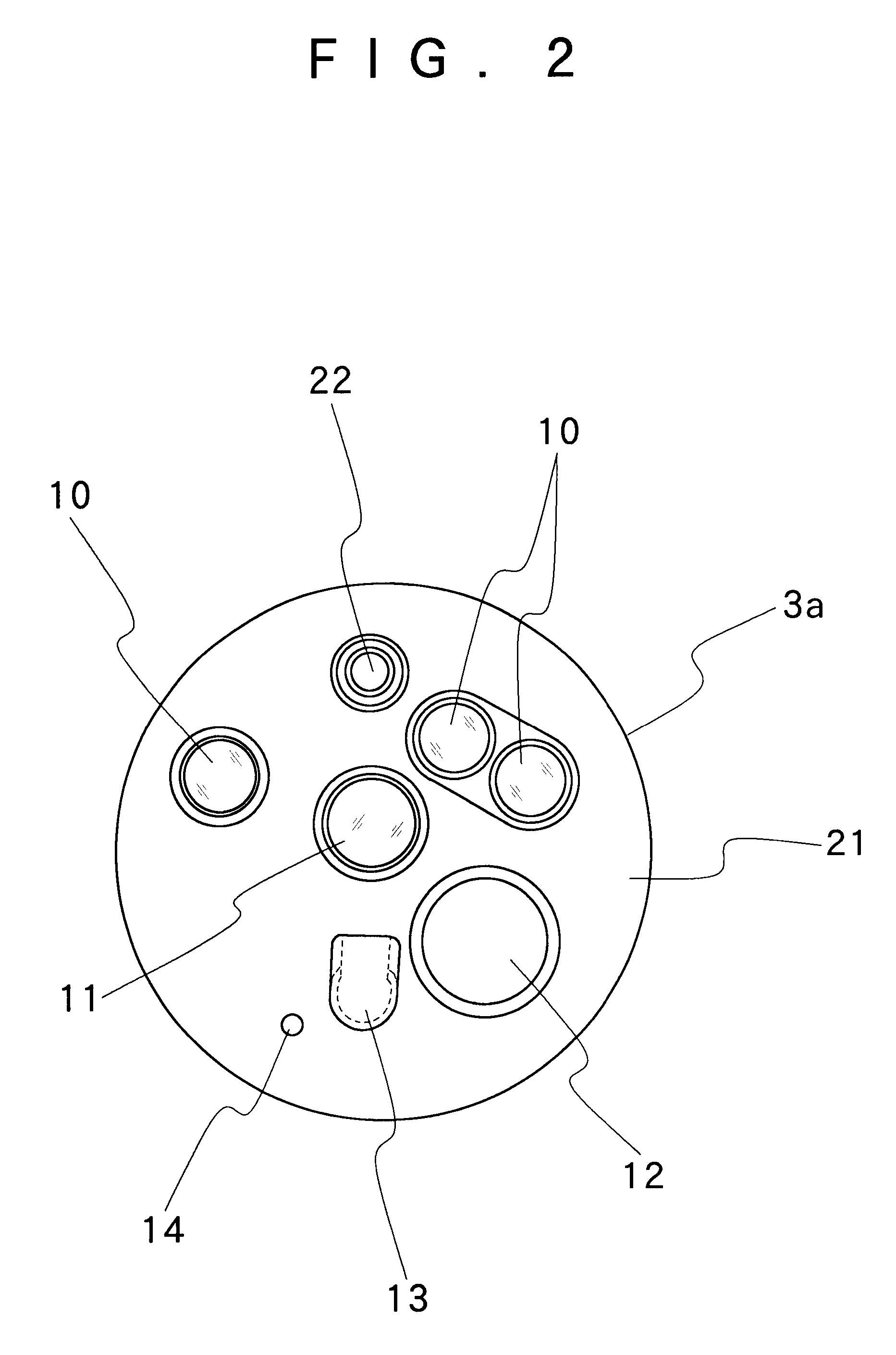
Hereafter, the present invention is described more particularly by way of its preferred embodiments. In the following description, the present invention is illustrated by way of an electronic endoscope employing a solid-state image sensor and an optical objective lens system incorporating a prism to bend an optical axis at right angles or through 90 degrees. However, it is to be understood that the present invention can be similarly applied to optical endoscopes having an image guide located at the focus of an objective lens system or to other electronic endoscopes having no prism in an objective lens system.

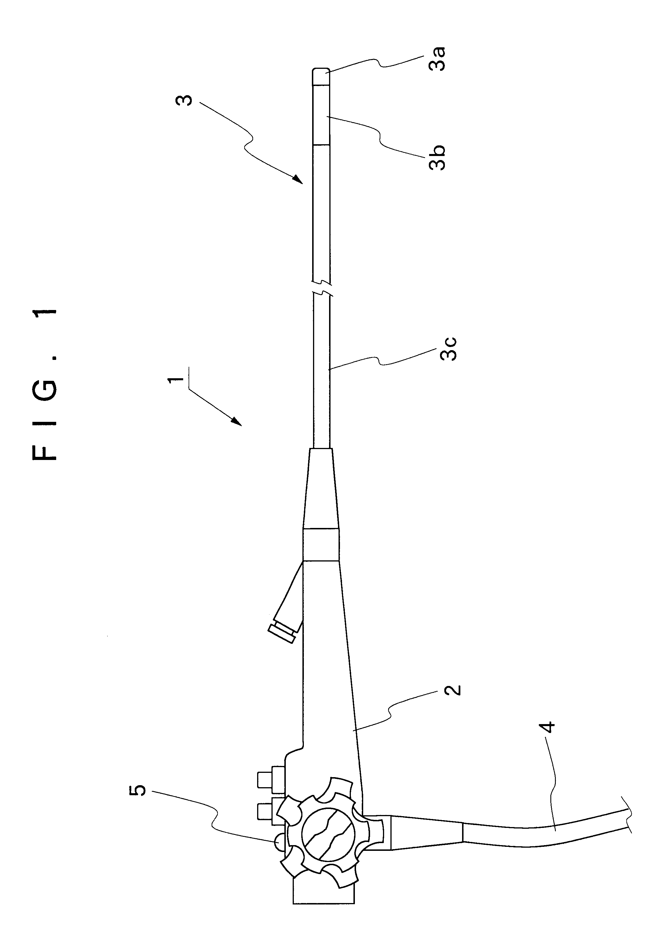
Shown schematically in FIG. 1 is a layout of an endoscope as a whole. As seen in that figure, an endoscope 1 is largely constituted by a manipulating head assembly 2, an insertion instrument 3 which is extended out on the front side of the manipulating head assembly 2, and a universal cable 4 which is led out from the manipulating head assembly 2. The insertion instrument is com...


PUM


Abstract

An endoscope with an objective lens drive mechanism for an objective lens system which is mounted within a rigid tip end section of an insertion instrument of the endoscope. The objective lens system includes a fixed lens which is mounted on a fixed lens frame, and at least one movable lens which is mounted on a movable lens frame. The movable lens frame is slidable along guide surfaces which are provided on the inner periphery of the fixed lens frame in the direction of optical axis of the lens system. A nut portion, which is projected from the movable lens frame substantially in a direction perpendicular to the optical axis, is held in threaded engagement with a screw rod member which is rotatably supported on a bearing member which is in turn supported on the fixed lens frame. The screw rod member is rotatable but blocked against movements in the axial direction. Further, the screw rod is connected with a flexible transmission shaft which is sheathed in a sleeve to transmit rotation to the screw rod. A control cable of the objective lens drive is constituted by the flexible transmission shaft and the sleeve.

Description

1. Field of the ArtThis invention relates to an endoscope for medical use, incorporating an objective lens drive mechanism in association with an optical objective lens system on its insertion instrument, and more particularly to an endoscope with an objective lens drive mechanism permitting to shift the position of at least one lens element of an optical objective lens system in the direction of its optical axis by remote control to vary at least observation depth, image magnification scale or view field angle.2. Prior ArtIn general, endoscopes which are used for medical purposes are largely constituted by a manipulating head assembly to be gripped by an operator to control the operation of the endoscope, an insertion instrument extended out on the front side of the manipulating head assembly for insertion into a body cavity, and a universal cable led out from the manipulating head assembly for connection to a light source. In terms of construction and function, the insertion instr...

Claims


Application Information

Patent Timeline
IPC IPC(8): A61B1/00
CPCA61B1/00096A61B1/00188A61B1/00101
Inventor MITSUMORI, NAOTAKE
Owner FUJI PHOTO OPTICAL CO LTD
Learn More