Circuit for controlling current levels in differential logic circuitry

a technology of differential logic and circuits, applied in analogue and hybrid computing, instruments, and arbitrarily function generators, etc., can solve the problems of ecl circuits with relatively high power consumption, and large power consumption of ecl circuits

Inactive Publication Date: 2002-06-25
STMICROELECTRONICS SRL
View PDF6 Cites 31 Cited by
  • Summary
  • Abstract
  • Description
  • Claims
  • Application Information

AI Technical Summary

Problems solved by technology

The speed of the ECL and other differential logic circuits is mainly limited by the capacitances of the bipolar transistors therein.
Because current continuously flows through a branch of an ECL circuit, a drawback of ECL circuits is the relatively high power consumption thereof.
It can be seen that differential logic circuits designed to operate at the highest possible speed operate at relatively high current levels and thus dissipate a relatively high amount of power.
However, such high current levels are unnecessary for lower frequency applications.
However, the resulting voltage swing is not compatible with standard ECL technology and varies with temperature.
However, the circuitry for performing the current and resistance adjustments is relatively complex.

Method used


Image

  • Circuit for controlling current levels in differential logic circuitry
  • Circuit for controlling current levels in differential logic circuitry
  • Circuit for controlling current levels in differential logic circuitry

Examples


Embodiment Construction

The present invention will now be described more fully hereinafter with reference to the accompanying drawings in which a preferred embodiment of the invention is shown. The embodiment is provided so that this disclosure will be thorough and complete, and will fully convey the scope of the invention to those skilled in the art.

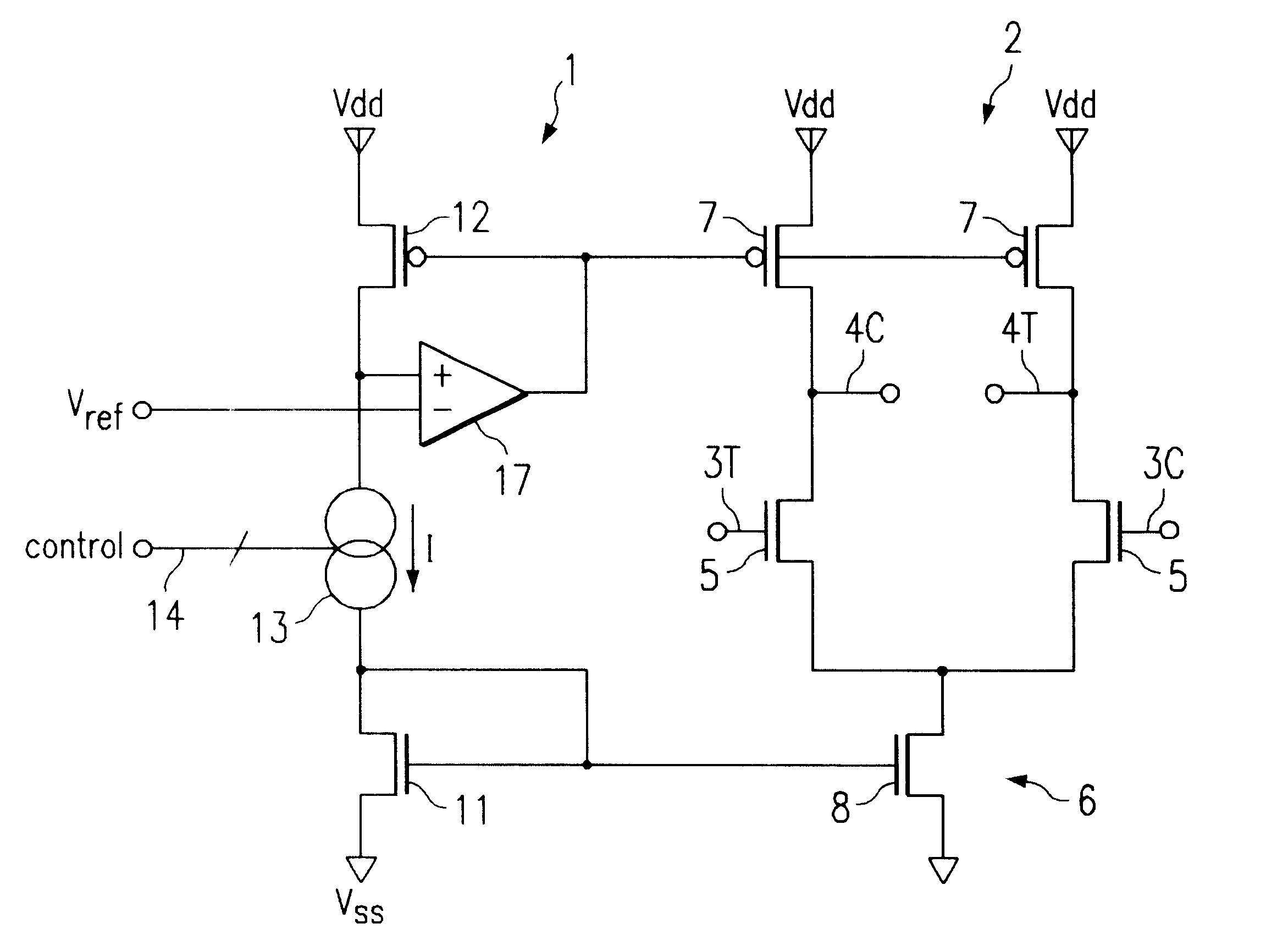
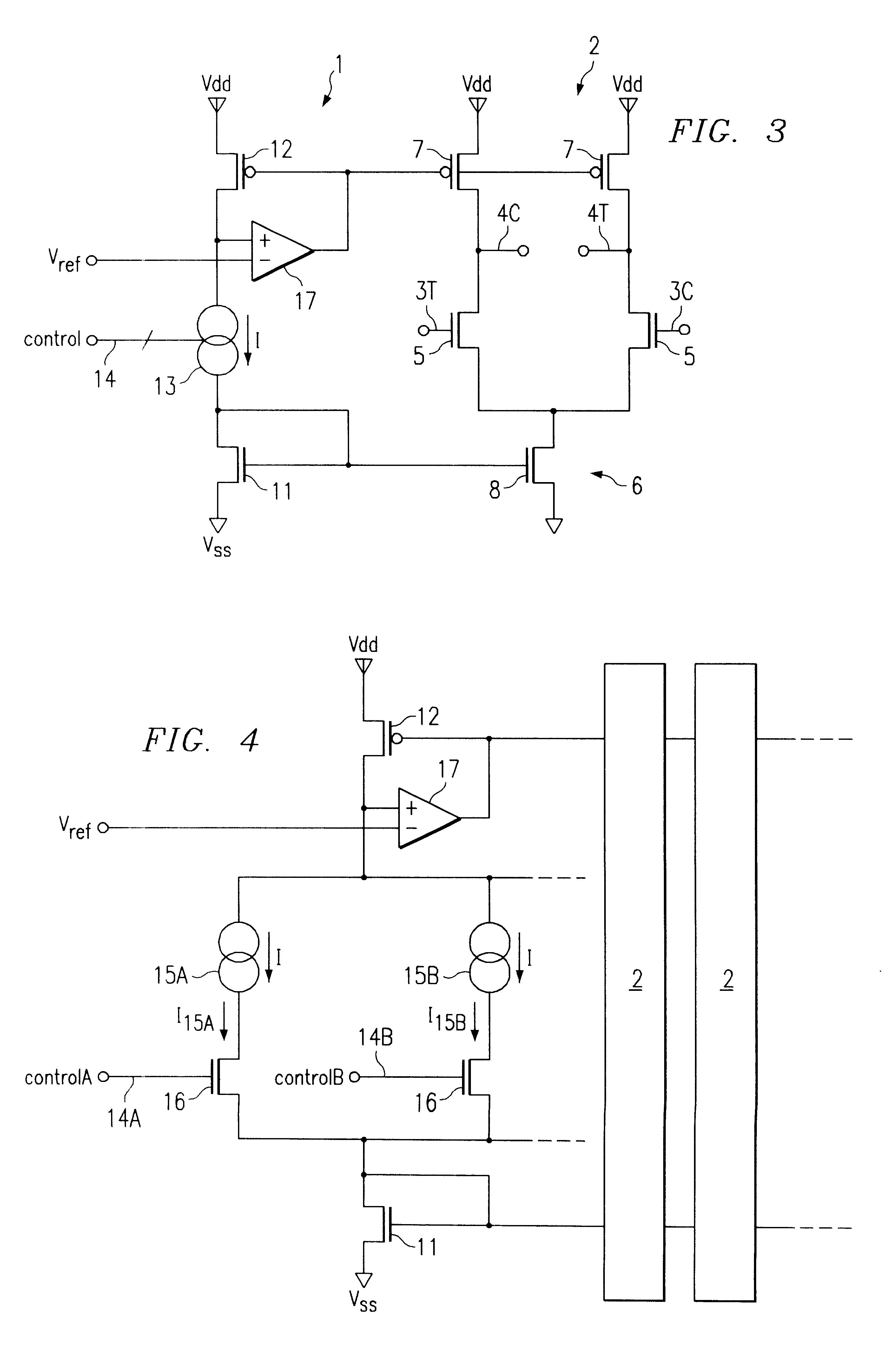
Referring to FIGS. 3 and 4, there is shown a control circuit 1 for setting the current level of a differential logic circuit 2. Differential logic circuit 2 is adapted to receive at least one pair of differential input signals 3 (3T and 3C) and steer current along one of a plurality of current paths between the positive supply Vdd and negative supply Vss based upon differential input signals 3T and 3C. Differential logic circuit 2 may be a conventional differential logic circuit having at least one pair of input transistors 5 for receiving the differential input signals 3T and 3C, and a pair of differential output signals 4T and 4C. Each input transistor 5 inc...


PUM


Abstract

A method and circuit are disclosed for controlling the current level of a differential logic circuit having a current source, input transistors which perform current steering based upon the input to the differential logic circuit, and load transistors. The circuit includes a first transistor that forms a current mirror with the current source, a second transistor coupled to the load transistors so that the operating characteristics of the load transistors substantially match the operating characteristics of the second transistor, and current source circuitry coupled between the first and second transistors. The current level selected in the current source circuitry sets the current level in the differential logic circuit and the resistance of the load transistors so that the output voltage swing of the differential logic circuit stays within an acceptable range of voltages, regardless of the selected current level.

Description

1. Technical Field of the InventionThe present invention relates to controlling current levels in differential logic circuits, such as emitter-coupled logic (ECL) circuits and source-coupled logic (SCL) circuits, and particularly to setting the current levels in differential logic circuits without changing the output voltage swing thereof.2. Background of the InventionEmitter coupled logic (ECL) circuits are among the fastest types of integrated circuits. To obtain a high operating speed, ECL circuits are designed so that the bipolar transistors therein never saturate. The signals processed by ECL circuits are mostly differential signals, and each component of the differential signal is applied to a separate input of the differential circuit.FIG. 1 represents a conventional ECL inverter circuit. The collector terminals of bipolar transistors Ta and Tb are connected to a positive supply Vdd through respective load resistors R and a bias current source I is connected between the emitt...

Claims


Application Information

Patent Timeline
Patent Type & Authority Patents(United States)
IPC IPC(8): G05F3/24G05F3/08
CPCG05F3/242
Inventor CALLAHAN, JR., MICHAEL J.
Owner STMICROELECTRONICS SRL
Why Eureka
Try Eureka