
Game machine

a game machine and game technology, applied in the field of game machines, can solve the problems of short-circuit or wire breakage, wiring could be torn off, and the methods and forms of such changeable indications or unique performance effects become more advanced or complicated

Inactive Publication Date: 2002-07-09
UNIVERSAL ENTERTAINMENT CORP
View PDF9 Cites 14 Cited by
  • Summary
  • Abstract
  • Description
  • Claims
  • Application Information

AI Technical Summary

Problems solved by technology

Methods and forms of such changeable indication or unique performance effects become more advanced or complicated corresponding to development of microcomputer technology and advanced needs from players in recent years.
However, upon assembling parts during manufacturing, the wirings are possibly broken at its outer sheaths by legs of IC projecting from the substrate, a pointed tool, or any of various protuberances in the working environment, thereby causing a short-circuit or breaking of wire.
The wirings could be torn off by an inadvertent handling during removal or transportation.
Furthermore, the signal transmission means such as wiring which can be easily accessible or touched from the outside is susceptible to suffer troubles by pranks or unlawful actions.

Method used


Image

  • Game machine
  • Game machine
  • Game machine

Examples


first embodiment

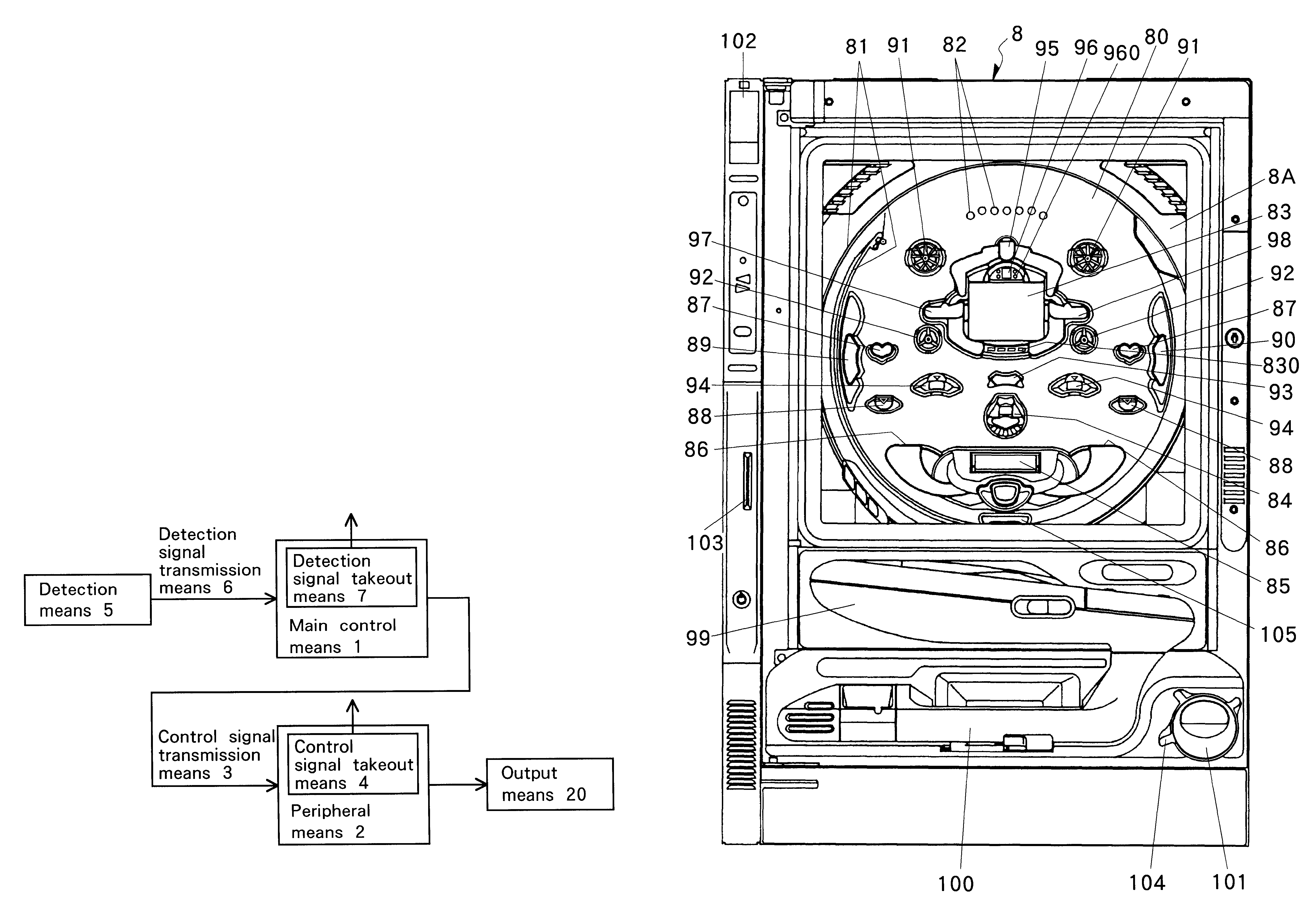
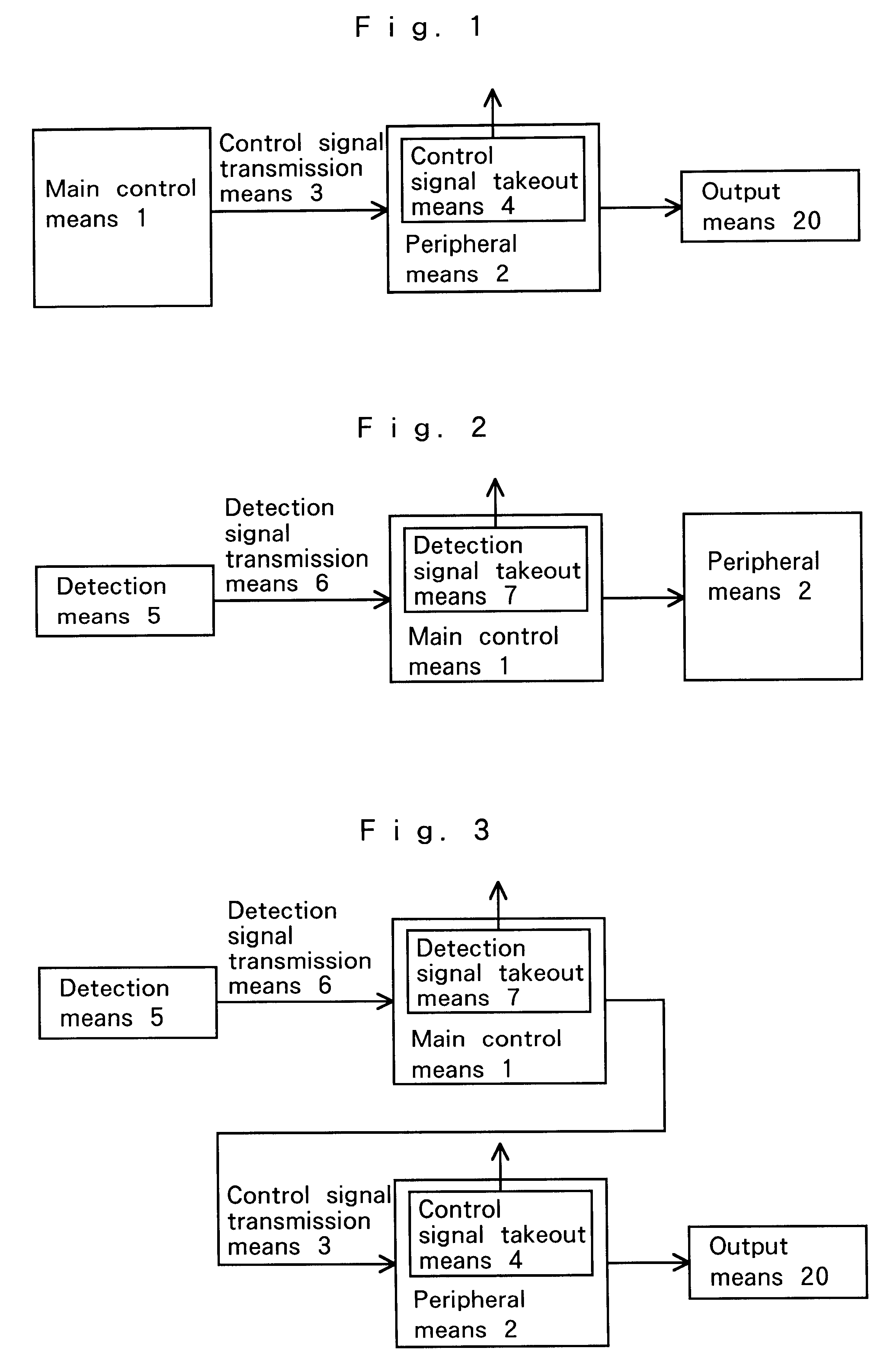
FIG. 8 shows a control signal takeout means 4, which takes out control signals transmitted by the control signal transmission means 3 at a point after a connection to a peripheral means 2 such as a indication control device 21 to the outside, or a detection signal takeout means 7, which takes out detection signals transmitted by detection signal transmission means 6 at a point after a connection to the main control means 1. In this case, a signal takeout terminal is integrally formed at the connector IN part to connect with a measuring device or testing tools.

second embodiment

FIG. 9 shows the control signal takeout means 4 or detection signal takeout means 7. In this case, pins, through-holes, lands, or connectors may be provided on the way of wiring pattern extending from output, for example, of input buffer, forming the I / O part, thereby enabling connection with measuring devices or testing tools.

third embodiment

FIG. 10 shows the control signal takeout means 4 or detection signal takeout means 7. In this case, signals which first input in CPU and taken out through output port can be monitored. Pins, through-holes, lands, connectors may be provided on the way of wiring pattern extending from the output port, thereby enabling connection with measuring devices or testing tools.

The control signal takeout means 4 and detection signal takeout means 7 do not need the same construction. The structures of FIGS. 8 to 10 may be used in proper combination. For example, the control signal takeout means 4 may use a structure of FIG. 9 while the detection signal takeout means 7 may be structured as in FIG. 8. Though not shown, in FIG. 8, pins, through holes, lands, connectors may be provided on the way of wiring pattern extending from the input connector IN, thereby enabling connection with measuring devices or testing tools.

In the above, explanation is omitted for control of various lamps and sounds from...


PUM


Abstract

A game machine. The game machine includes a main control means (1), a peripheral device (2), a control signal transmission device (3), and a control signal takeout device (4) which takes out control signals transmitted by the main control device (1) via the control signal transmission device (3) to the outside at a point after a connection to the peripheral device (2) and is connectable with a measuring device, such as a tester, an oscilloscope, or a digital analyzer, or an examining tool, such as a personal computer, an exclusive testing monitor.

Description

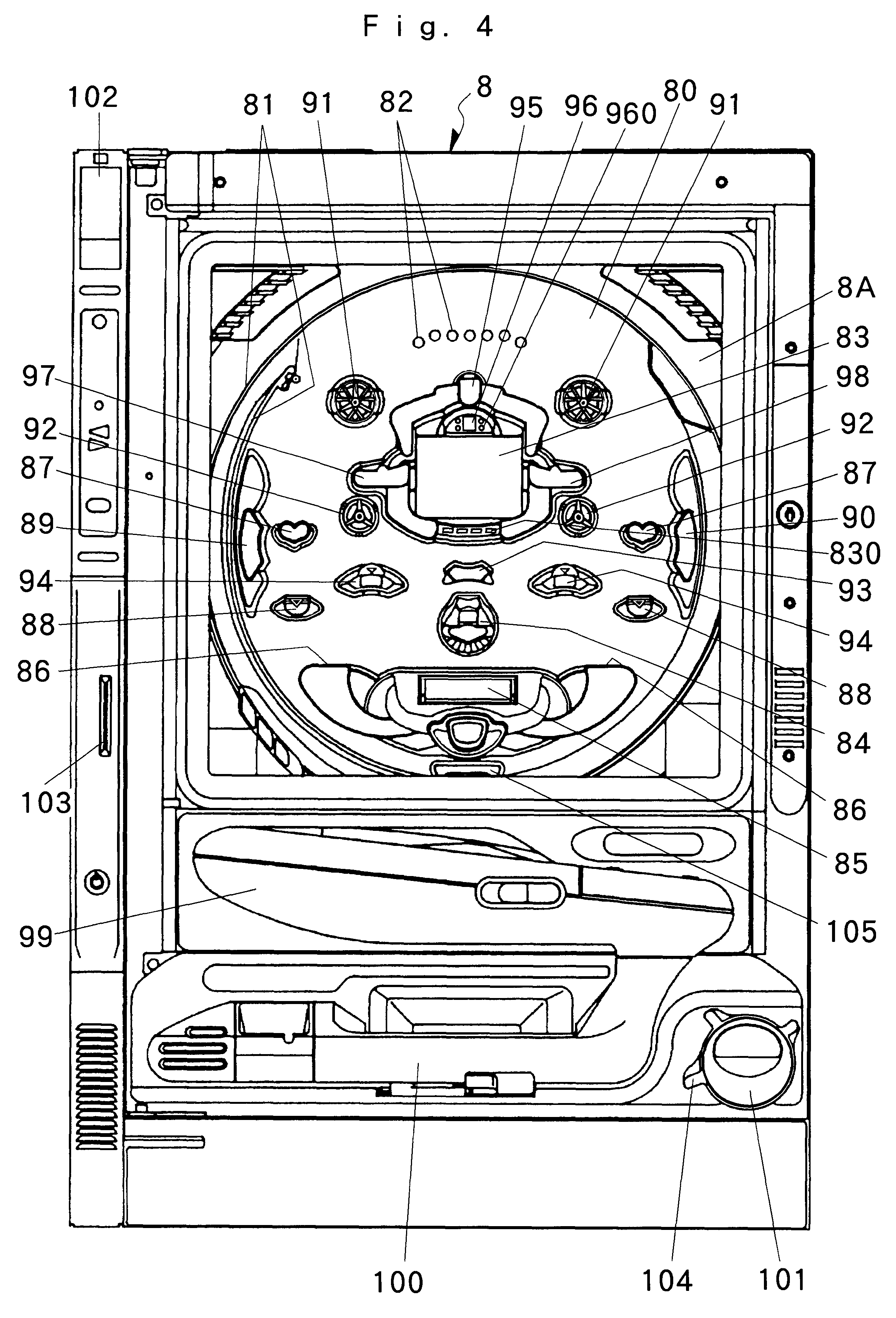
1. Field of the InventionThe invention relates to an improvement of a game machine, such as a ball-flicking type including a so -called "Pachinko", "Arrange-ball", and "Majong-ball", a reel-rotating type called "Pachi-slot", or a slot machine.2. Description of the Related ArtPrior art game machines allow a special pattern indication device using liquid crystal display, CRT, or a mechanical reel to perform changeable indication corresponding to changes of progress of games, for example, occurrence of a ball's falling into a special operation-start hole, or allow a lamp(s) and / or an amplifier(s) to make unique performance effects. Methods and forms of such changeable indication or unique performance effects become more advanced or complicated corresponding to development of microcomputer technology and advanced needs from players in recent years.Hence, most of such kinds of game machines are designed, for reducing loads to a micro-processor, to employ a main CPU, which adapted for mai...

Claims


Application Information

Patent Timeline
IPC IPC(8): G07F17/32A63F7/02
CPCG07F17/32G07F17/3202
Inventor KAMIMURA, MASATO
Owner UNIVERSAL ENTERTAINMENT CORP
Learn More