Method for mold changing in heated glass sheet forming station
Inactive Publication Date: 2002-07-16
GLASSTECH
View PDF29 Cites 30 Cited by
Summary
Abstract
Description
Claims
Application Information
AI Technical Summary
This helps you quickly interpret patents by identifying the three key elements:
Problems solved by technology
Method used
Benefits of technology
An object of the present invention is to provide an improved method for changing a heated mold
Problems solved by technology
The heated environment also makes it more difficult to change molds
Method used
Image
Click on the blue label to locate the original text in one second.
Reading with bidirectional positioning of images and text.
Examples
Embodiment Construction
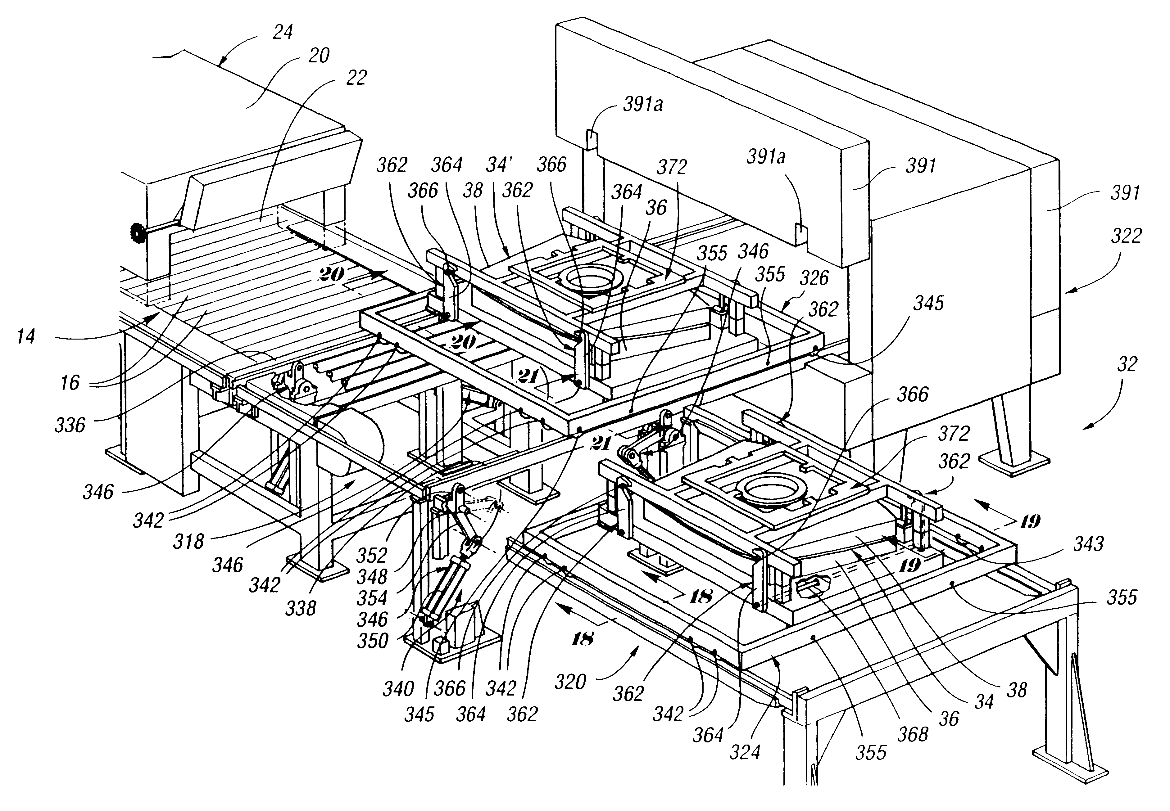
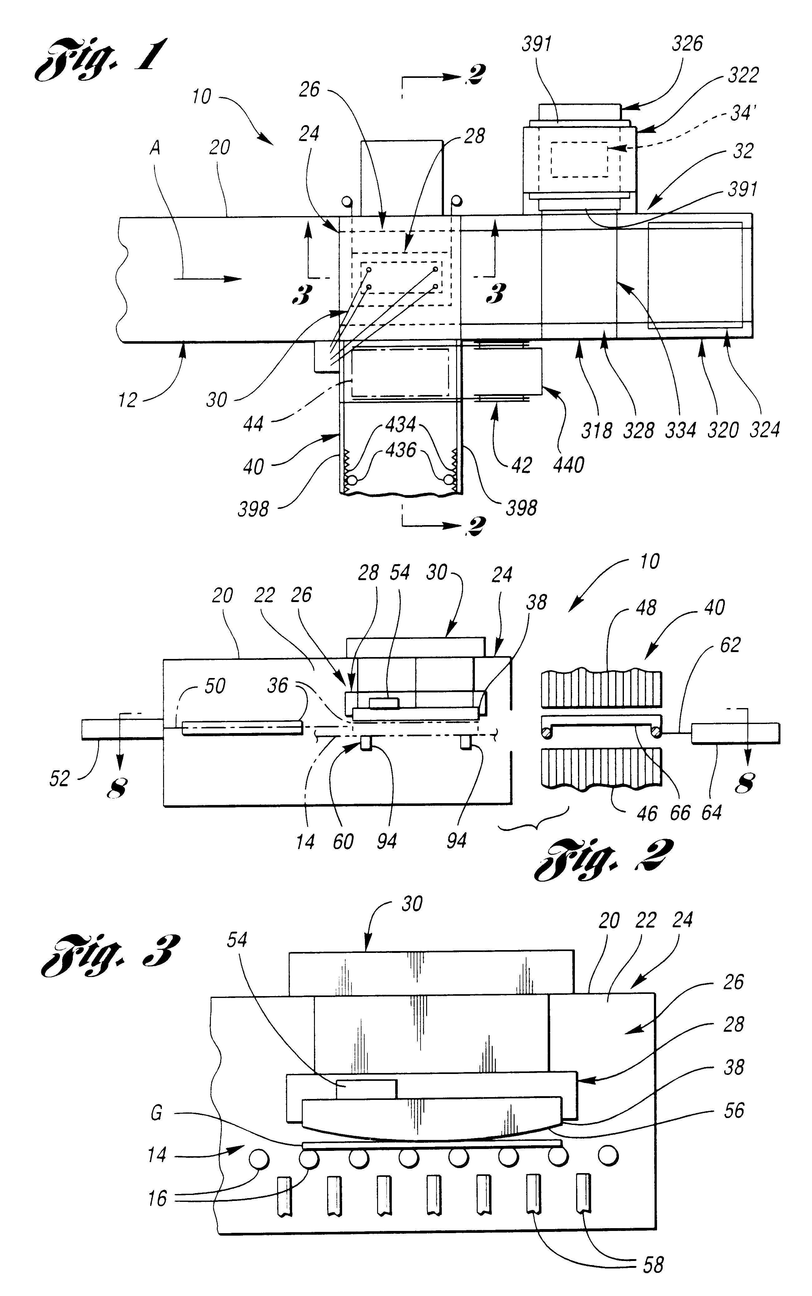
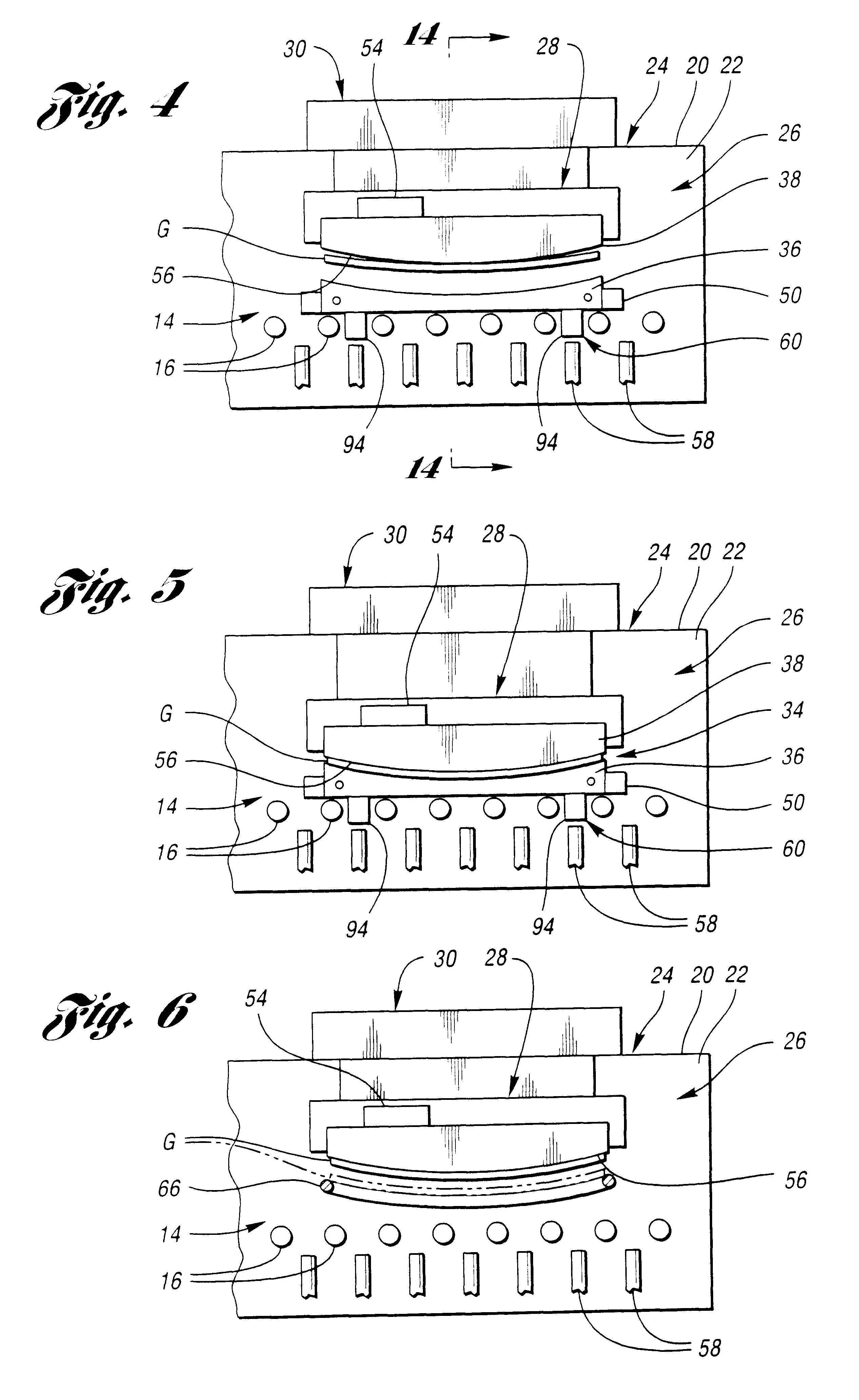
With reference to FIG. 1 of the drawings, a glass sheet forming and quench system for performing the invention is generally indicated by 10 and will be summarily described before a detailed description of each station, apparatus, and method of operation utilized to perform the forming and quenching of glass sheets. System 10 includes an elongated furnace 12 in which glass sheets are heated during movement along a primary system axis A, which movement is also referred to as a direction of conveyance through the system. The conveyance within the furnace 12 may be on a roll conveyor 14 that includes rolls 16 as illustrated in FIGS. 2-7. As specifically shown in FIG. 7, the glass sheets are introduced into the system 10 at a loading table 18 for movement into a system housing 20 that defines a heated chamber 22 as shown in FIGS. 2-6.
With continuing reference to FIG. 1, the glass sheets after heating to forming temperature are moved to the right to a forming station 24 that includes appa...
PUM
Abstract
A method for heated mold changing at a forming station (24) is performed by apparatus (32) in a heated chamber (22) where heated glass sheets are cyclically formed. A switching station (318) is located adjacent the forming station (24). An unloading station (320) and a mold preheating station (322) are each located adjacent the switching station. An unloading cart (324) is initially movable from the loading station (320) to the switching station (318) and then to the forming station (24) to receive one or more heated molds from the forming station and is subsequently moved from the forming station back through the switching station to the unloading station to permit unloading of each heated mold. A loading cart supports a second mold or a pair of molds for heating within the mold preheating station (322) and is movable from the mold preheating station to the switching station (318) and then to the forming station for mold loading.
Description
This invention relates to a method for changing a heated mold at a forming station in a heated chamber where the mold cyclically forms heated glass sheets.Glass sheets are conventionally formed by heating within a furnace and then forming within a heated chamber prior to delivery for cooling. Such cooling can be slow cooling to provide annealing or faster cooling that provides heat strengthening or tempering. In connection with heating of the glass sheets, see U.S. patent Nos.: U.S. Pat. No. 3,806,312 McMaster et al.; U.S. Pat. No. 3,947,242 McMaster et al.; U.S. Pat. No. 3,994,711 McMaster; U.S. Pat. No. 4,404,011 McMaster; and U.S. Pat. No. 4,512,460 McMaster. In connection with glass sheet forming, see U.S. patent Nos.: U.S. Pat. No. 4,282,026 McMaster et al.; U.S. Pat. No. 4,437,871 McMaster et al.; U.S. Pat. No. 4,575,390 McMaster; U.S. Pat. No. 4,661,141 Nitschke et al.; U.S. Pat. No. 5,004,491 McMaster et al.; and U.S. Pat. No. 5,472,470 Kormanyos et al. In connection with th...
Claims
Application Information
Patent Timeline
Application Date:The date an application was filed.
Publication Date:The date a patent or application was officially published.
First Publication Date:The earliest publication date of a patent with the same application number.
Issue Date:Publication date of the patent grant document.
PCT Entry Date:The Entry date of PCT National Phase.
Estimated Expiry Date:The statutory expiry date of a patent right according to the Patent Law, and it is the longest term of protection that the patent right can achieve without the termination of the patent right due to other reasons(Term extension factor has been taken into account ).
Invalid Date:Actual expiry date is based on effective date or publication date of legal transaction data of invalid patent.