Mining machine with sliding cutting tool assembly

a cutting tool and mining machine technology, applied in cutting machines, props/chocks, speech analysis, etc., can solve the problem of relatively restricted free space required for safe anchorage near the mine fa

Inactive Publication Date: 2002-08-06
VOEST ALPINE BERGTECHNIK GMBH
View PDF14 Cites 4 Cited by
  • Summary
  • Abstract
  • Description
  • Claims
  • Application Information

AI Technical Summary

Benefits of technology

The machine frame, which carries the guides for the slide in the plane of the crawlers of the track-laying gear, in an advantageous manner may comprise suitable upwardly directed mounting means, such as a mounting plate or mounting spars for arranging anchor boring and setting devices, merely on its front end facing the crossbeam, so that those anchor boring and setting devices likewise may be hinged to, or supported on, the machine frame in a low-structured manner so as to provide for a large pivoting range and hence a large working range for the anchor boring and setting devices. This is of particular importance not least because of the fact that anchors having lengths of several meters may be employed for a reliable anchorage, which anchors at an accordingly low articulation of the anchor boring and setting devices to the machine frame, can be safely introduced into the anchor boring and setting devices, and hence set, without cumbersome manipulations.
A particularly efficient anchor boring and setting operation may be safeguarded if at least two anchor boring and setting devices arranged in a V-shaped manner on a common carrier are pivotably connected with the mounting plate or mounting spars of the machine frame, the common pivot axis being located on the level of a lower pivot axis of a multipart cantilever arm for cutting tools on the portal-like crossbeam of the slide, or below said pivot axis. Such an arrangement of the anchor boring and setting device and a pivot axis that is located on an accordingly low level enable the economic introduction of the total anchor section required while additionally enhancing the support of the machine frame by means of the supporting props arranged on the supporting consoles.

Problems solved by technology

While it has already been possible to substantially reduce the structural height in the known configurations, the free space required for a safe anchorage near the mine face still has remained relatively restricted.

Method used


Image

  • Mining machine with sliding cutting tool assembly
  • Mining machine with sliding cutting tool assembly
  • Mining machine with sliding cutting tool assembly

Examples


Embodiment Construction

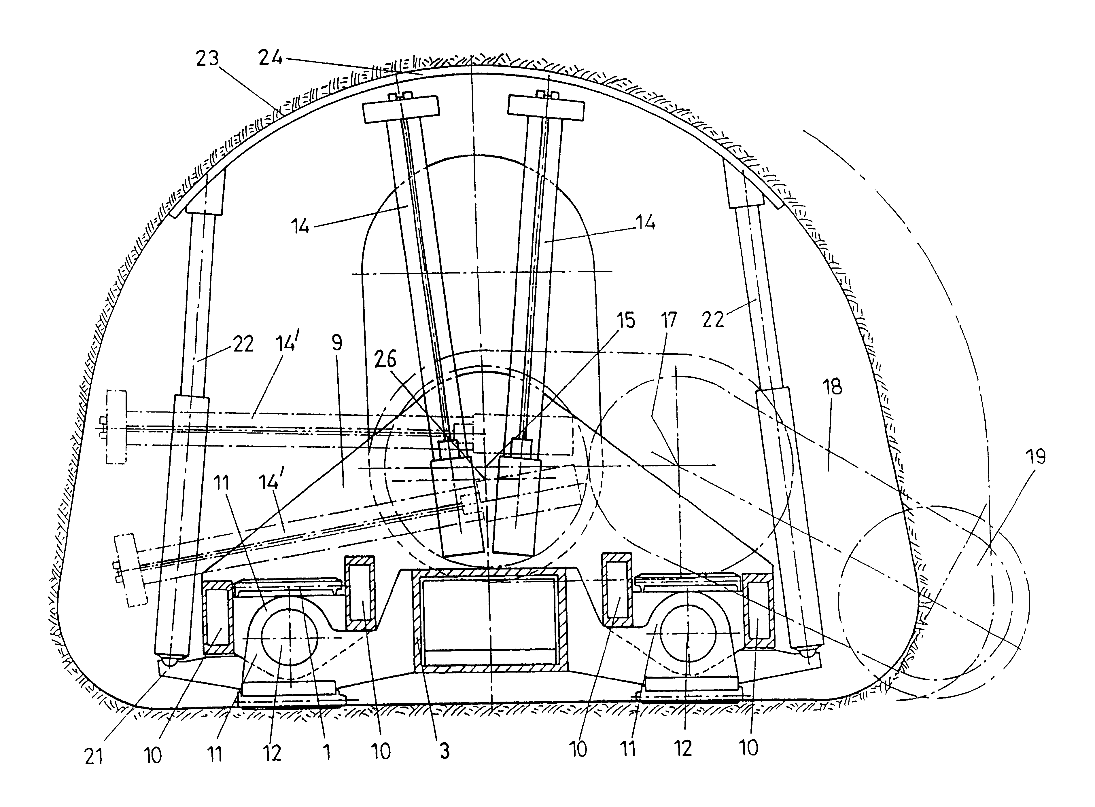
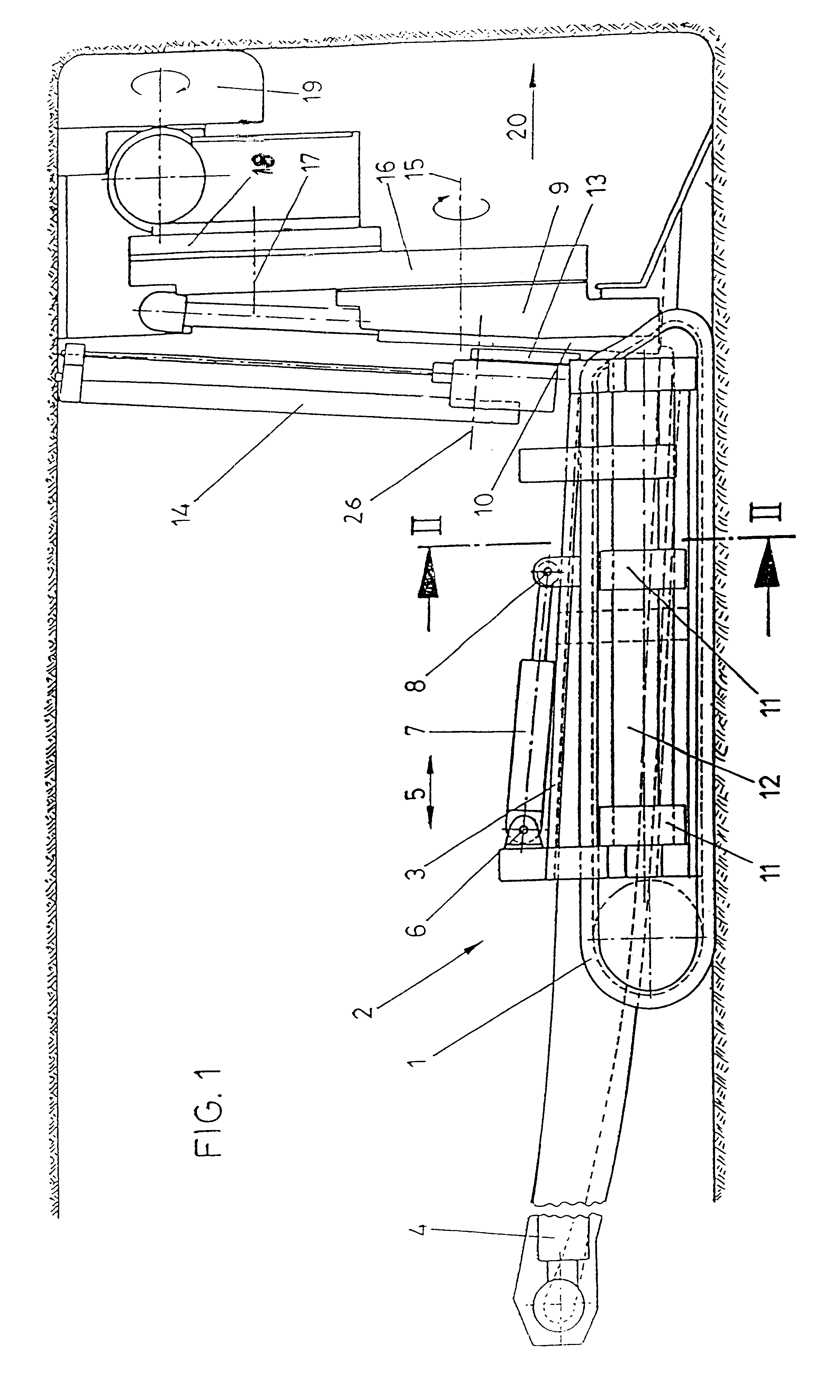
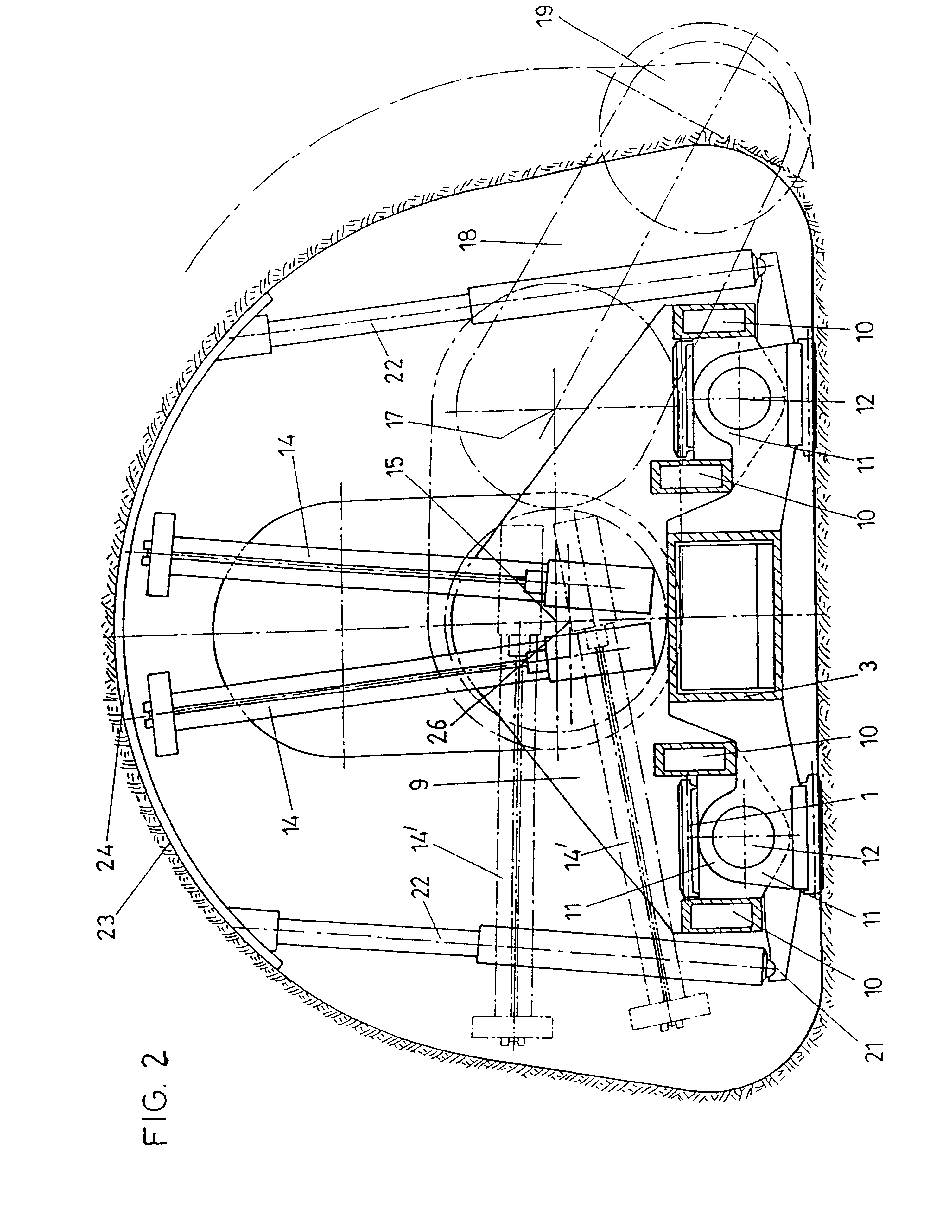
In FIG. 1, a track-laying gear of a cutting machine 2 is denoted by 1. The machine frame is designed as a box section 3, in which a hauling means, whose rear end is schematically indicated by 4, is displaceably mounted in the direction of the double arrow 5. This box section 3, which is stationary relative to the track-laying gear, constitutes a torsionally firm machine frame to whose rear end a hydraulic cylinder piston unit 7 is hinged via a lug 6, contacting the displaceable slide at 8. The displaceable slide comprises a portal-likely designed crossbeam 9 which is connected with longitudinaly carriers or longitudinal spars 10 extending in the longitudinal direction of the machine. These longitudinal spars 10 again are connected with lugs 11 encompassing guide tubes or rods 12. These guide tubes or rods 12 in the plane of the track-laying gear 1 are each rigidly connected with the machine frame comprising said box section 3. Upon actuation of the hydraulic cylinder piston unit 7, ...


PUM


Abstract

In a cutting machine (2), including rotatably mounted cutting or shearing tools (19), a loading ramp and a hauling means (4) extend in a direction towards a mine face for receiving and hauling cut or sheared material. The cutting or shearing tools (19) are mounted on a slide which is displaceable on guides extending in the longitudinal direction of the machine. The guides are comprised of tubes or rods connected with a machine flame in the region of the track-laying gears (1), preferably within the track-laying gear frame. The slide is comprised of longitudinal spars (10) and a crossbeam (9) for mounting the cutting or shearing tools (19). The machine frame, at least in its front region adjacent the crossbeam (9), is designed as a box section (3), within the clear width of which the hauling means (4) is guided in a manner so as to be displaceable in the longitudinal direction of the machine.

Description

This application is the national phase of international application PCT / AT98 / 00269 filed Nov. 3, 1988 which designated the U.S.1. Field of the InventionThe invention relates to a cutting machine including rotatably mounted cutting of shearing tools, a loading ramp and a hauling means extending in the direction towards the mine face for receiving and hauling the cut of sheared material, in which the cutting or shearing tools are mounted on a slide which is displaceable on guides extending in the longitudinal direction of the machine.2. The Prior ArtDE-A1 40 18 154 describes a cutting machine in which the entire machine frame of an advance working machine is designed to be displaceable relative to the track-laying gear. The guiding means are arranged to extend in the longitudinal direction of the machine on both sides of the track-laying gear, with the guiding elements that are connected with the track-laying gear being encompassed. The entire machine frame is displaced in the longitu...

Claims


Application Information

Patent Timeline
Patent Type & Authority Patents(United States)
IPC IPC(8): E21C27/24E21D9/10E21D15/58E21C27/00E21D20/00E21D15/00E21D20/02
CPCE21C27/24E21D9/1026E21D15/58E21D20/028G10L2019/0005
Inventor LERCHBAUM, KARLKOGLER, PETER
Owner VOEST ALPINE BERGTECHNIK GMBH
Why Eureka
Try Eureka