Locking differential with clutch activated by magnetorheological fluid

a magnetorheological fluid and differential technology, applied in mechanical actuated clutches, gearing, transportation and packaging, etc., can solve the problem of prior art differentials, the relative rotational speed between the output shafts of two wheels exceeds a predetermined limit, and the reliance on fluid expansion does not provide fine control over the amount of relative rotation required

Inactive Publication Date: 2002-08-06
TORQUE TRACTION TECH INC
View PDF11 Cites 52 Cited by
  • Summary
  • Abstract
  • Description
  • Claims
  • Application Information

AI Technical Summary

Problems solved by technology

If one of the wheels begins to slip, however, the relative rotational speed between the output shafts of the two wheels exceeds a predetermined limit.
There are drawbacks to such prior art differentials.
Relying on fluid expansion does not provide fine control over the amount of relati...

Method used


Image

  • Locking differential with clutch activated by magnetorheological fluid
  • Locking differential with clutch activated by magnetorheological fluid
  • Locking differential with clutch activated by magnetorheological fluid

Examples


Embodiment Construction

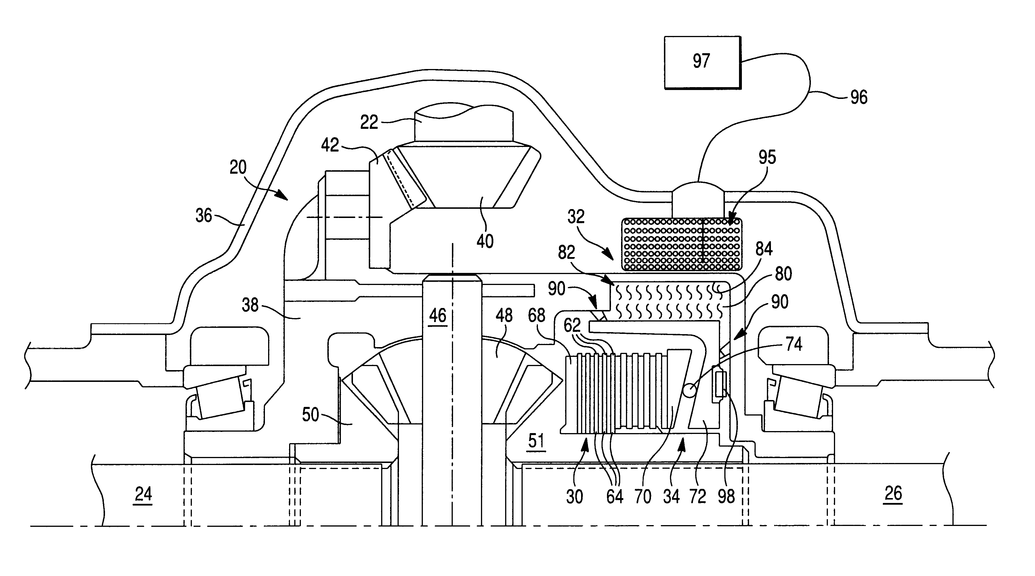
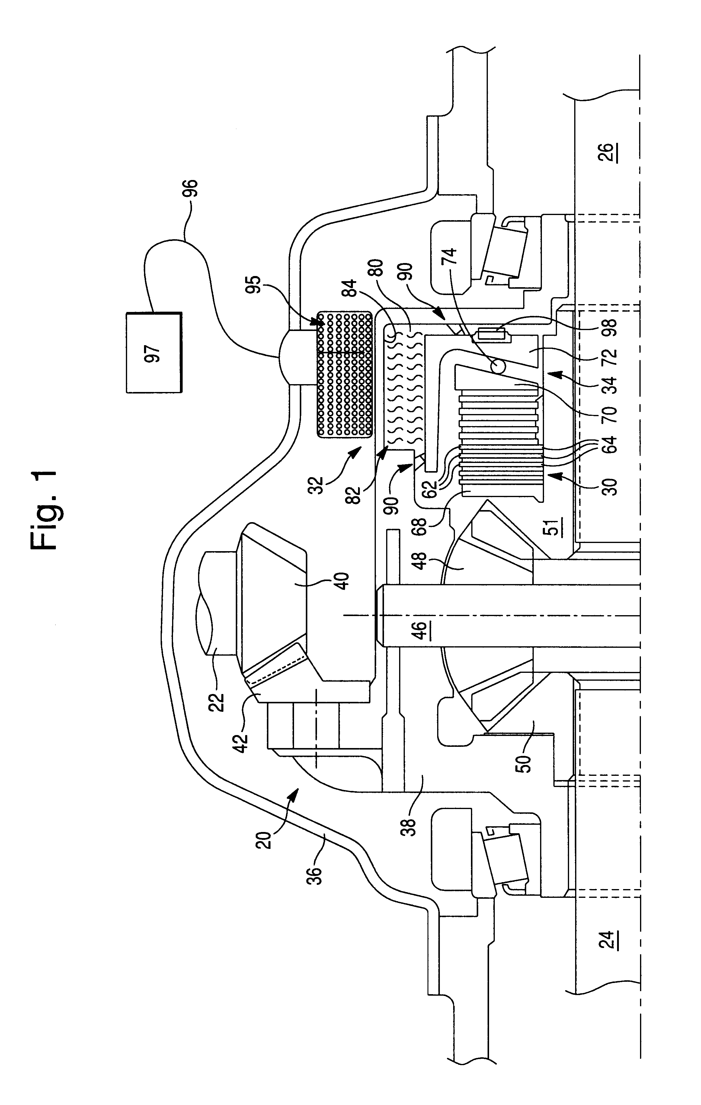
Referring now to the drawings, FIG. 1 illustrates a differential gear assembly 20 including an input drive shaft 22, a left output shaft 24 and a right output shaft 26. Left output shaft 24 and right output shaft 26 extend along a common output drive axis 28. The left and right directions are defined as shown in FIG. 1.

To limit the relative rotational speed between output shafts 24 and 26, differential gear assembly 20 includes a clutch mechanism 30, an electromagnetic actuator 32 and a camming mechanism 34. As will be explained, the electromagnetic actuator 32 reacts to an undesirably large relative rotational speed between output shafts 24 and 26. Camming mechanism 34 is responsive to a displacement from electromagnetic actuator 32 to provide a force to selectively engage clutch mechanism 30 and directly connect output shafts 24 and 26.

Differential gear assembly 20 is shown as a planetary differential including an outer housing 36 enclosing a rotatable one-piece differential gear ...


PUM


Abstract

A limited slip differential includes a friction clutch mechanism, an electromagnetic coupling, and a camming mechanism disposed between the friction clutch mechanism and the electromagnetic coupling. The camming mechanism converts shearing forces within the electromagnetic coupling to an axial force applied to engage the clutch mechanism. The camming mechanism includes annular discs having axially inclined ramps, and a roller bearing for movement along the ramps to provide for variable spacing between the annular discs, wherein increased spacing is used to apply the axial force.

Description

1. Field of the InventionThis invention relates to a limited slip differential which is actuated to limit the relative rotational speed between two driven shafts above a predetermined amount and, more particularly, to a drive line clutch having an electromagnet surrounding an annulus filled with magneto-rheological fluid.2. Description of Related ArtLimited slip differentials are known for providing rotational drive to two output shafts. In particular, such differentials are often used to drive the axles of motor vehicles. A limited slip differential allows relative rotation between two output shafts under certain circumstances. For example, when a vehicle turns, the output shaft of the outer wheel typically turns at a higher rotational speed than the output shaft of the inner wheel. A limited slip differential allows this relative rotation. If one of the wheels begins to slip, however, the relative rotational speed between the output shafts of the two wheels exceeds a predetermined...

Claims


Application Information

Patent Timeline
IPC IPC(8): F16H48/00F16H48/30F16D27/115F16D28/00F16H48/20F16D37/00F16H48/22F16H48/26F16H48/34
CPCF16H48/22F16H48/26F16H48/30F16H48/34F16H2048/204F16H2048/346
Inventor HUNT, WILLIAM GORDON
Owner TORQUE TRACTION TECH INC
Why Eureka
Try Eureka