Small-sized coreless motor

Inactive Publication Date: 2002-08-06
NAMIKI SEIMITSU HOSEKI KK
View PDF20 Cites 7 Cited by
  • Summary
  • Abstract
  • Description
  • Claims
  • Application Information

AI Technical Summary

Benefits of technology

The purpose of this invention is to provide a coreless miniature motor, including vibrating coreless motors and gyro motors, with superior portability in terms of small size and l

Problems solved by technology

The eccentric weight 4 mounted on the axis that protrudes outside the external housing 1 of this coreless motor presents a major obstacle to efforts to make portable electronic equipment such as pagers and mobile telephones smaller and lighter.
Moreover, because the eccentric weight 4 spins about with support on one side, the load of the spinning is particularly heavy on the bearing 3, and a loss of torque occurs.
Moreover, if the equipment undergoes a fall or shock, the heaviness of the weight 4 can bend the rotating shaft 2; it is not possible to make the shaft 2 with a very small diameter.
In addition to the eccentric weight and the e

Method used


Image

  • Small-sized coreless motor
  • Small-sized coreless motor
  • Small-sized coreless motor

Examples


Embodiment Construction

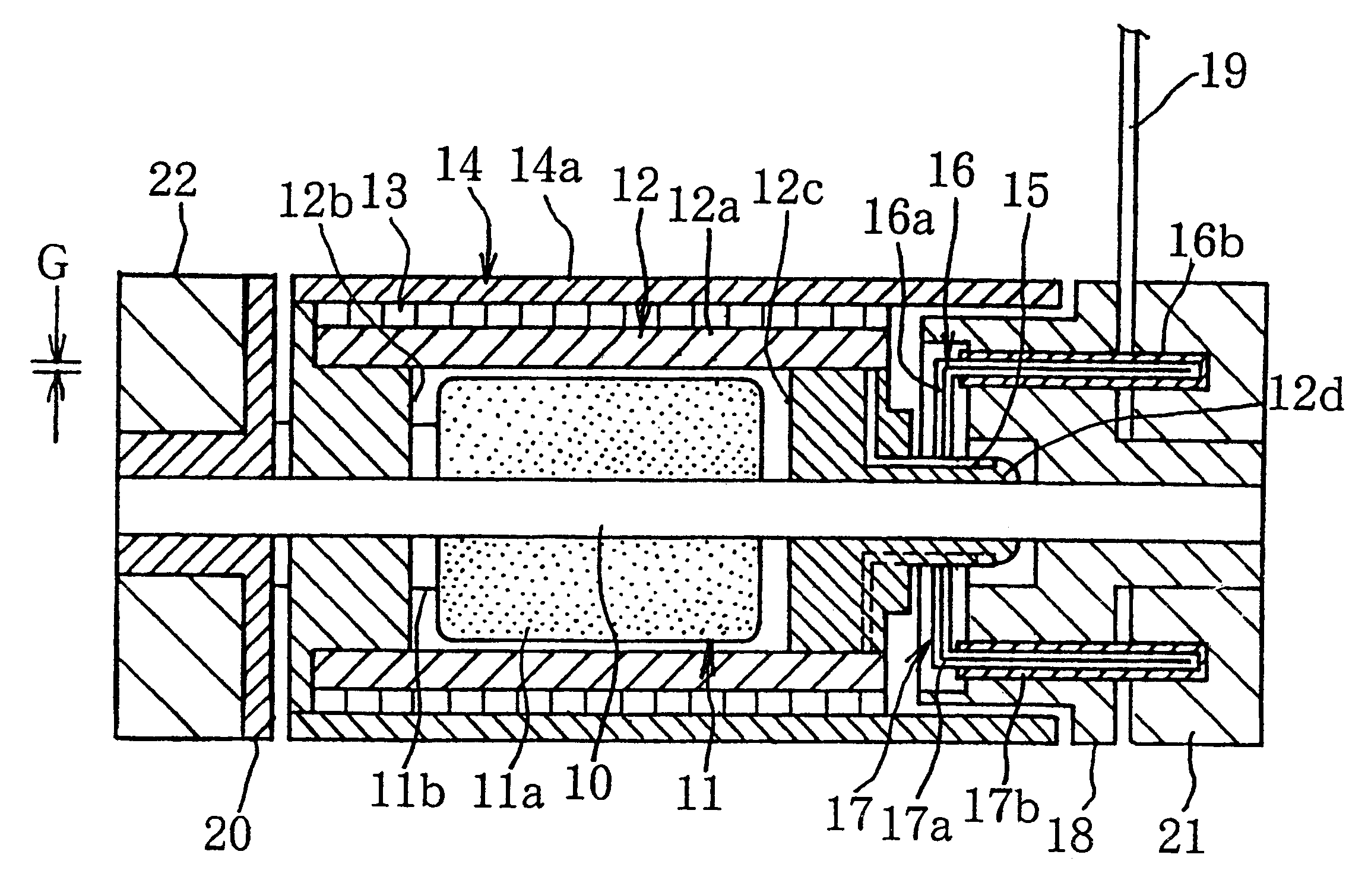
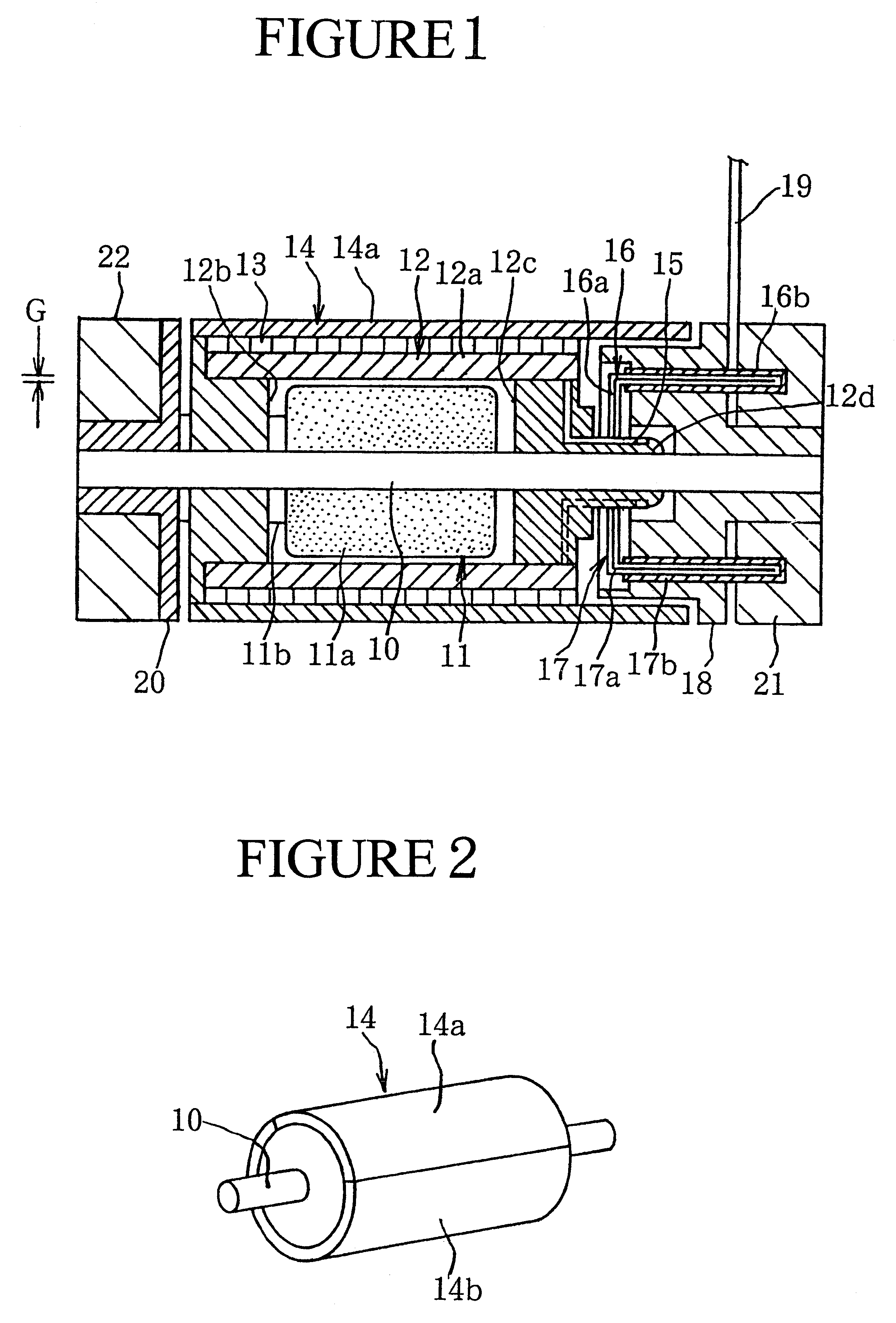
This invention is explained in detail below, with reference to FIGS. 1 to 8. This invention constitutes a coreless miniature motor, or coreless motor or gyro rotor, used to generate vibrations. In place of the conventional motor assembled with a rotating shaft and a rotor that includes a coil, the coreless miniature motor has, as shown in FIG. 1, a main part which is a fixed shaft 10 held in place on both ends by brackets attached as described below, assembled with a stator 11, a rotor 12 and other parts, and with the rotor 12 also serving as an eccentric weight.

With the fixed shaft 10 as the main part, the stator 11 has the fixed shaft 10 inserted in a central position; the field magnet 11a is fitted onto the shaft roughly at its center, with its position along the axis determined by a spacer 11b.

The rotor 12 comprises a cylindrical coil 12a that contains within its inner diameter the field magnet 11a separated by a slight gap G, and rotor plates 12b, 12c that are free to turn on t...


PUM


Abstract

The motor as a whole is made smaller and lighter with a fixed shaft (10) as the main part, with this fixed shaft (10) inserted through and fixed to the center of a field magnet (11a) such that the field magnet (11a) placed roughly in the middle of the center axis of the fixed shaft (10) makes up the stator (11). The outer periphery of this field magnet (11a) is encompassed by the inner diameter of a cylindrical coil (12a), separated by a gap (G). Rotor plates (12b, 12c) are fitted so as to be free to rotate around the central axis of the fixed shaft (10) on both sides of the field magnet (11a), and these rotor plates (12b, 12c) are fitted into the ends of the coil (12a) and with it make up the rotor (12). A cylindrical yoke (13) is placed around the outer periphery of the coil (12a) and forms a single unit with it, and eccentric plates (14) around the outer periphery of the yoke make up the eccentric weight.

Description

FIELD OF TECHNOLOGYThis invention deals with a coreless, miniature motor. In more detail, it deals with improvement of a miniature motor for use in assembly of pagers, mobile telephones and other portable electronic equipment, to serve as a vibration alarm device that rings by vibration.PRIOR TECHNOLOGYVibration alarm devices that ring by vibration instead of ringing by sound have been adopted as alarm devices to notify one of received messages in conferences and other locations where production of a sound is to be avoided.Conventionally, vibration alarm devices of this sort have used coreless motors that rotate an eccentric weight.Such a coreless motor has, as shown in FIG. 9, an external housing 1 that comprises a cylindrical case 1a and caps 1b and 1c that fit into both ends of the case 1a, a central rotating shaft 2 of which one end projects through the cap 1b at one end of the case 1a and the other end is located within the case 1a; the rotating shaft 2 is supported and free to...

Claims


Application Information

Patent Timeline
IPC IPC(8): H02K7/06H02K5/14H02K5/167H01R39/00H01R39/24
CPCH02K5/145H02K5/1675H02K7/063H01R39/24
Inventor HISAFUMI, YASUDA
Owner NAMIKI SEIMITSU HOSEKI KK
Why Eureka
Try Eureka