Infrared ear thermometer

a thermometer and infrared technology, applied in the field of temperature measurement, can solve the problems of large detector too large to be inserted into the ear canal leading to the tympanic membrane, non-zero emisivity, and relatively high cos

Inactive Publication Date: 2002-08-20
GERLITZ JONATHAN
View PDF79 Cites 75 Cited by
  • Summary
  • Abstract
  • Description
  • Claims
  • Application Information

AI Technical Summary

Problems solved by technology

As conventionally mounted, the detector is too large to be inserted into the ear canal leading to the tympanic membrane.
The use of a waveguide involve

Method used


Image

  • Infrared ear thermometer
  • Infrared ear thermometer
  • Infrared ear thermometer

Examples


Embodiment Construction

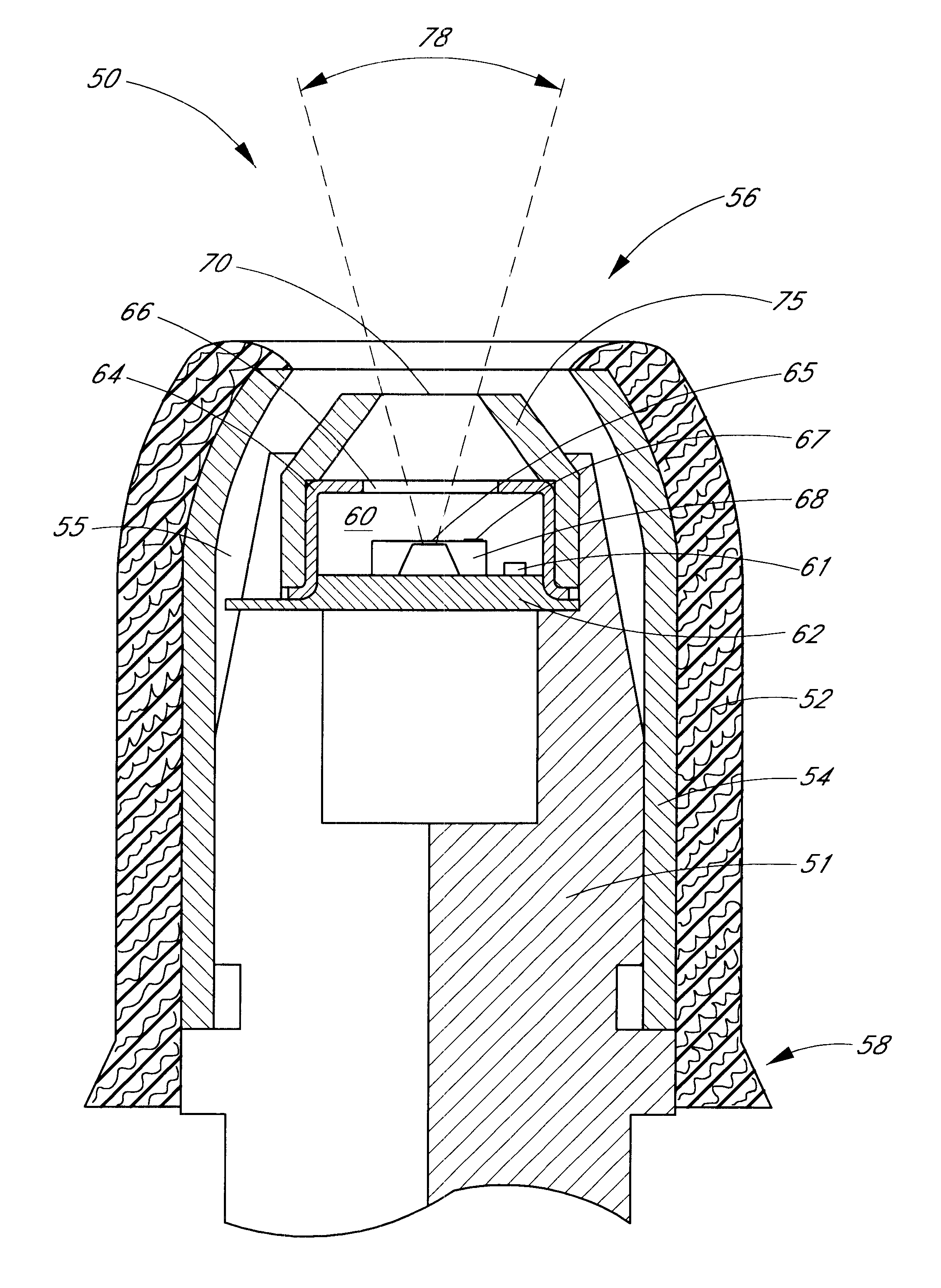
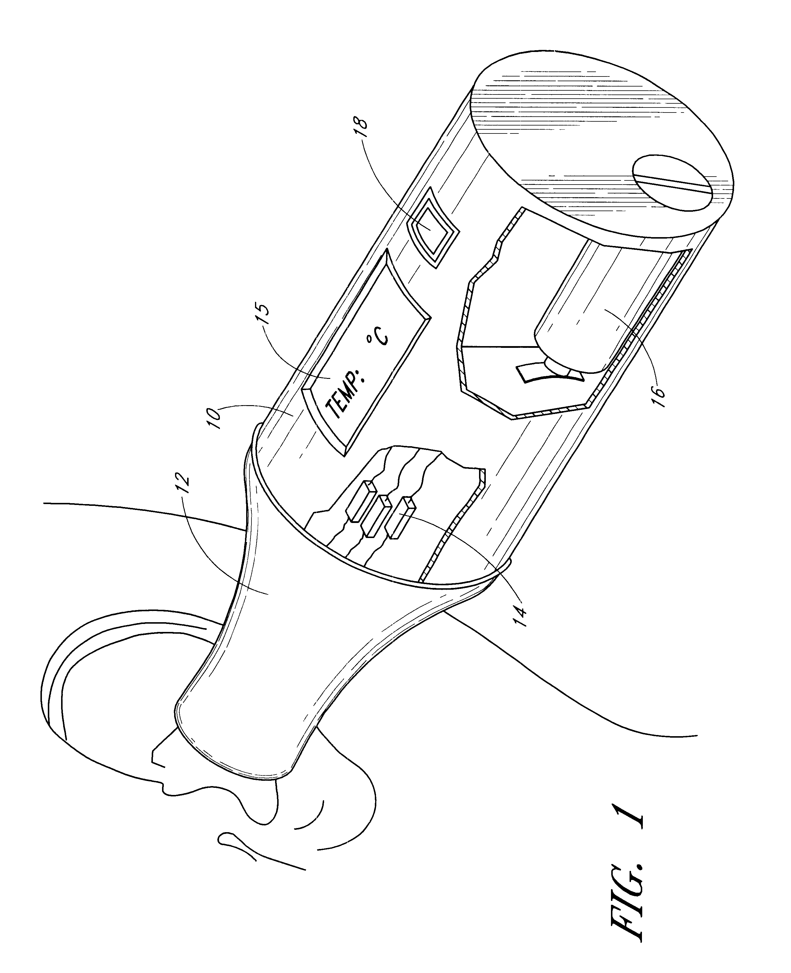
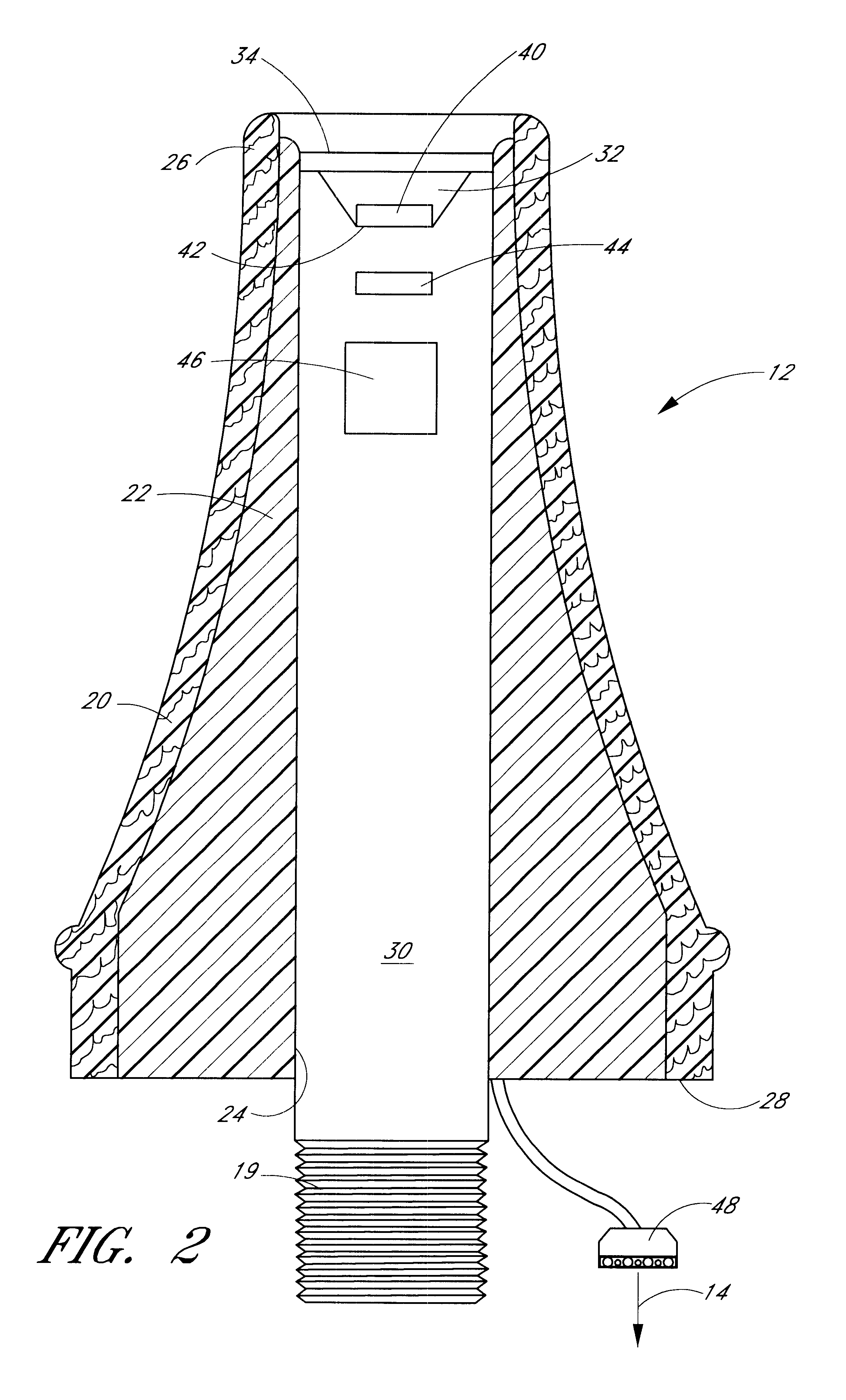
In the following description, reference is made to the accompanying drawings, which form a part hereof, and which show, by way of illustration, specific embodiments in which the invention may be practiced. It is to be understood that other embodiments may be utilized and structural changes may be made without departing from the scope of the present invention. Where possible, the same reference numbers will be used throughout the drawings to refer to the same or like components. Numerous specific details are set forth in order to provide a thorough understanding of the present invention. However, it will be understood by one skilled in the art that the present invention may be practiced without the specific details or with certain alternative equivalent devices and methods to those described herein. In other instances, well-known methods, procedures, components, and devices have not been described in detail so as not to unnecessarily obscure aspects of the present invention.

FIG. 1 il...


PUM


Abstract

An infrared ear thermometer includes a detector head housing, a heat sink, a recess formed in the heat sink, a thermopile sensor mounted within the recess, a thermistor, and temperature determination circuitry. The recess defines an aperture that limits the field of view of the thermopile sensor. The thermal capacities and conductivities of the heat sink and the thermopile sensor are selected so that the output signal of the thermopile sensor stabilizes during a temperature measurement. A method of determining temperature using the ear thermometer takes successive measurements, stores the measurements in a moving time window, averages the measurements in the moving window, determines whether the average has stabilized, and outputs an average temperature. A method of calculating a subject's temperature determines the temperature of a cold junction of the thermopile, looks up a bias and slope of the thermopile based upon the temperature of the cold junction, measures the output of the thermopile, and calculates the subject's temperature based upon a linear relationship between the output and the subject's temperature. The linear relationship is defined by the bias and the slope.

Description

This application claims the benefit of priority under 35 U.S.C. .sctn. 119(a) from Israeli Patent Application No. 126224, filed on Sep. 15, 1998.1. Field of the InventionThis invention relates generally to temperature measurement and, more particularly, the invention relates to infrared clinical thermometers.2. Description of the Related ArtConventional ear thermometers employ an infrared (IR) detector for sensing the temperature inside the ear at the tympanic membrane. The infrared detector is mounted within a heat sink so as to stabilize an ambient reference temperature. As conventionally mounted, the detector is too large to be inserted into the ear canal leading to the tympanic membrane. Accordingly, a waveguide, typically formed of a polished tube, is interposed between the tympanic membrane and the IR detector. The use of a waveguide involves a number of drawbacks resulting, for example, from its non-zero emissivity, its relatively high cost, and the complexity of the resultan...

Claims


Application Information

Patent Timeline
IPC IPC(8): G01K13/00A61B5/01G01J5/03G01J5/04G01J5/16G01J5/10
CPCG01J5/02G01J5/0275G01J5/028G01J5/04G01J5/049G01J5/06G01J5/061G01J5/16G01J2005/068G01J5/064
Inventor GERLITZ, JONATHAN
Owner GERLITZ JONATHAN
Why Eureka
Try Eureka