System and method for non-intrusive thermal monitor

a thermal monitor and non-intrusive technology, applied in the field of temperature sensors, can solve the problems of slowed response time, time delay, slow device responsiveness, etc., and achieve the effect of increasing the performance and lifespan of these components, and fast and accurate manners

Inactive Publication Date: 2010-06-01
ENTEGRIS INC
View PDF160 Cites 36 Cited by
  • Summary
  • Abstract
  • Description
  • Claims
  • Application Information

AI Technical Summary

Benefits of technology

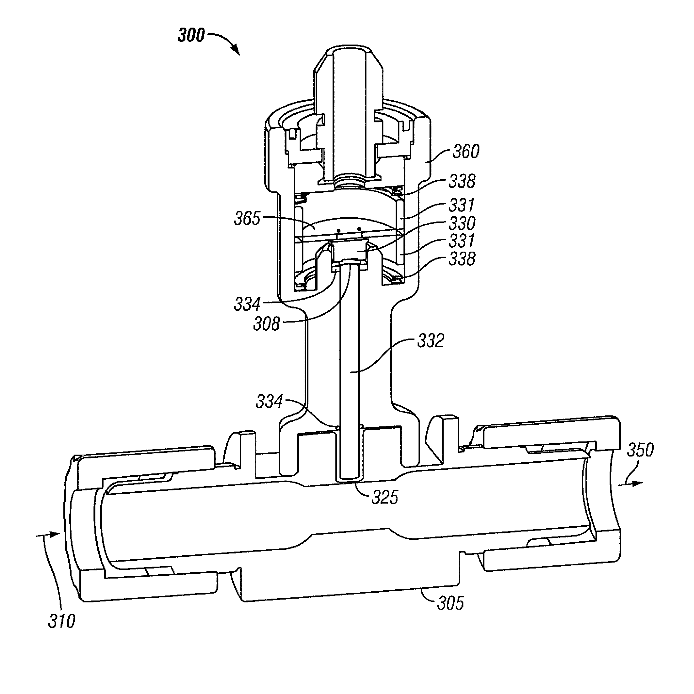
[0005]Embodiments disclosed herein provide systems, methods and apparatuses for fast and non-intrusive temperature sensing of a fluid, which may be particularly useful in semiconductor manufacturing applications with a fluid flow. In some embodiments, the non-intrusive temperature sensors can take temperature measurements in a fast and accurate manner without having any direct contact with a liquid. Moreover, embodiments disclosed herein can advantageously isolate electronic and / or optical components from the fluid, increasing the performance and lifespan of these components. In some embodiments, the electronic and / or optical components can be calibrated and / or serviced separate from a fluid housing and without having to shut down the fluid system.
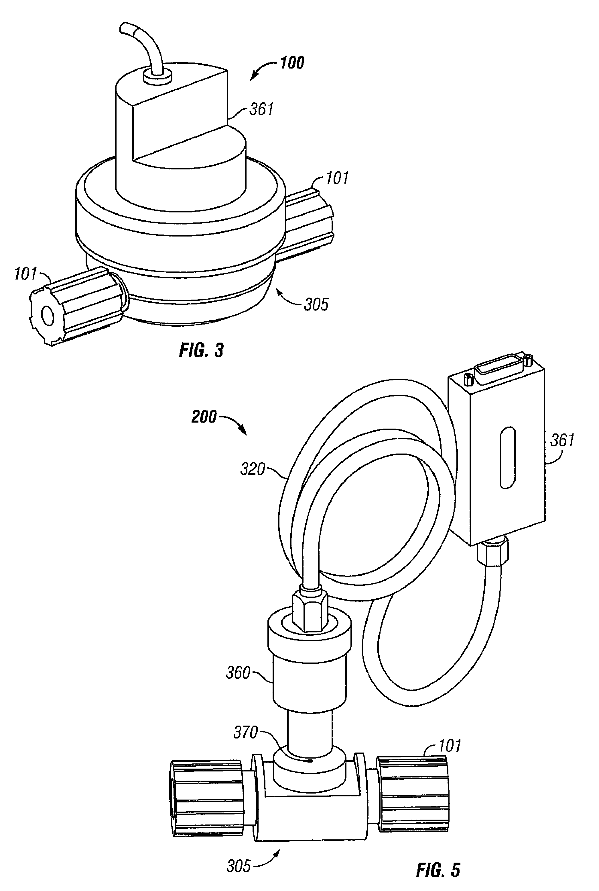
[0006]In some embodiments, the non-intrusive temperature sensors utilize optical temperature measurement devices. In some embodiments, the optical temperature measurement devices are infrared (IR) temperature sensors. The utilization of an IR temperature sensor such as a thermopile addresses the response time issues, enabling embodiments to provide much shorter response times. IR temperature sensors are known to have the ability to measure the temperature in automobile manufacturing and food processing. However, no known IR temperature sensors are available specifically for semiconductor liquid applications. Embodiments disclosed herein take advantages of IR temperature sensors and provide non-intrusive solutions that can sample and monitor fluid temperatures in a manner that is particularly useful for semiconductor manufacturing applications. Embodiments disclosed herein do not have to be installed directly in the fluid path. They can be positioned near the fluid path or in a remote location. By positioning the sensor and electronics away from the fluid path, the thermal variations that the sensor and electronics are exposed to are minimized which could affect the speed and accuracy of temperature sampling. A high degree of temperature sensitivity and accuracy can thus be achieved. Higher temperature applications are also achievable using this method.
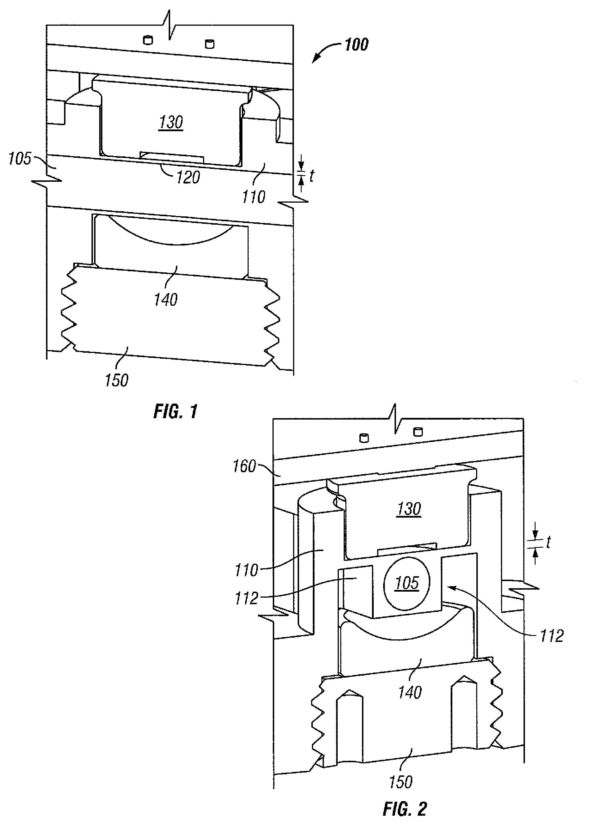
[0007]One embodiment of a non-intrusive thermal monitor comprises a thermopile and a fluid window. One embodiment of a non-intrusive thermal monitor comprises a thermopile, a fluid window, and a restrictor. In one embodiment, the fluid velocity can be increased at a sensor window location by restricting the flow path at the sensor window location. This has the advantage of avoiding measurement of just the outer boundary layer fluid temperature.
[0014]Embodiments of a non-intrusive thermal sensor disclosed herein have many advantages including, but not limited to, separation of fluid and signal processing electronics, flow path changes that cause turbidity at the point of measurement and reduce the boundary layer thermal error, elimination of the need to use fiber optics with a remote sensor, optimization of window thickness for fast signal response time, and great accuracy and fast response time at a reasonable cost. Some embodiments can achieve accuracy within + / −0.2 degrees C. Some embodiments can achieve response time at about 200 milliseconds or less.
[0016]Embodiments may also be used in system configurations such as a thermal mixing application to control the flow and temperature of a fluid by mixing hot and cold water in the correct proportions resulting in the programmed flow rate and temperature. Improvements to this application can be implemented with the use of the current invention. The improved response time of the sensor over conventional temperature measurement devices reduces the time required to attain a new programmed temperature. The device also improves the stability of the control because of the reduced response time. Embodiments are non-intrusive which means that it does not have to be in contact with the fluid that it is measuring. Thermocouples or Resistance Temperature Detectors (RTDs) generally require a protective coating such as Teflon to protect against corrosive chemicals but which is not a good thermal conductor. The coating adds additional time to the already slow response. Thermopiles may be used without a coating. Some embodiments disclosed herein may be configured as a probe style device for fluid bath applications or sealing into an existing housing or fitting.

Problems solved by technology

This thermal mass generally results in a time delay.
As the probe is exposed to different temperatures, the thermal mass of the probe has to equilibrate to the temperature change resulting in a slowed response time.
However, this coating causes two critical issues for suppliers.
First, the coating is permeable causing the metal probe to degrade quickly in aggressive chemical applications so the device has to be changed-out frequently.
Second, the coating adds another layer of thermal mass further slowing down the responsiveness of the device.
However, no known IR temperature sensors are available specifically for semiconductor liquid applications.
In contrast, a thermocouple may not detect quick changes in temperature, such as a thermal pulse, because thermocouples would not have the ability to accurately observe sudden changes in the rate of temperature change nearly as fast as a thermopile.
Thermocouples or Resistance Temperature Detectors (RTDs) generally require a protective coating such as Teflon to protect against corrosive chemicals but which is not a good thermal conductor.
The coating adds additional time to the already slow response.

Method used


Image

  • System and method for non-intrusive thermal monitor
  • System and method for non-intrusive thermal monitor
  • System and method for non-intrusive thermal monitor

Examples


Embodiment Construction

[0037]The invention and the various features and advantageous details thereof are explained more fully with reference to the non-limiting embodiments that are illustrated in the accompanying drawings and detailed in the following description. Descriptions of well known starting materials, processing techniques, components and equipment are omitted so as not to unnecessarily obscure the disclosure in detail. Skilled artisans should understand, however, that the detailed description and the specific examples, while disclosing preferred embodiments, are given by way of illustration only and not by way of limitation. Various substitutions, modifications, additions or rearrangements within the scope of the underlying inventive concept(s) will become apparent to those skilled in the art after reading this disclosure.

[0038]As used herein, the terms “comprises,”“comprising,”“includes,”“including,”“has,”“having” or any other variation thereof, are intended to cover a non-exclusive inclusion....


PUM

PropertyMeasurementUnit
response timeaaaaaaaaaa
transmittanceaaaaaaaaaa
temperatureaaaaaaaaaa

Abstract

Embodiments disclosed herein provide a non-intrusive thermal (NIT) monitor for sensing temperatures useful for semiconductor manufacturing applications. In some embodiments, a NIT monitor comprises a thermopile, a fluid housing with a fluid window, and an elongated member positioned between the thermopile and the fluid window for transmitting or reflecting infrared signals corresponding to a temperature of a fluid in the fluid housing. The fluid housing may have a cross-sectional profile to enable the manipulation of the fluid flow under the fluid window, enhancing the speed and accuracy of the temperature sampling. The elongated member, which may be hollow and coated with gold, may an extended piece of the fluid housing or a part of an optics housing. In some embodiments, the NIT monitor is connected to a main conditioning circuit board via a cable for processing the temperature measurements at a remote location.

Description

RELATED APPLICATIONS[0001]This application claims priority from U.S. Provisional Patent Application No. 60 / 906,935, filed Mar. 14, 2007, entitled “SYSTEM, METHOD AND APPARATUS FOR NON-INTRUSIVE TEMPERATURE SENSING OF SEMICONDUCTOR FLUID,” U.S. Provisional Patent Application No. 61 / 020,306, filed Jan. 10, 2008, entitled “NON-INTRUSIVE THERMAL MONITOR,” and U.S. Provisional Patent Application No. 61 / 027,330, filed Feb. 8, 2008, entitled “SYSTEM, METHOD AND APPARATUS FOR NON-INTRUSIVE TEMPERATURE SENSING OF SEMICONDUCTOR FLUID,” the entire contents of which are expressly incorporated herein by reference for all purposes.TECHNICAL FIELD[0002]The present invention relates generally to temperature sensors and more particularly to embodiments of new and useful non-intrusive thermal monitors for monitoring fluid temperatures.BACKGROUND OF THE RELATED ART[0003]Temperature sensors used in semiconductor liquid applications generally have direct contact with the fluid from where the temperature...

Claims


Application Information

Patent Timeline
Patent Type & Authority Patents(United States)
IPC IPC(8): G01J5/00G01K1/00
CPCG01J5/0037G01J5/02G01J5/12G01J5/08G01J5/0893G01J5/0255
Inventor LAVERDIERE, MARCMCLOUGHLIN, ROBERT F.CLARKE, MICHAELMAENKE, DALEWILKINSON, WILEY JAMES
Owner ENTEGRIS INC
Why Eureka
Try Eureka