
Fuse relay junction block for use in automobiles

a fuse relay and junction block technology, applied in the direction of printed circuit components, printed circuit casings/cabinets/drawers, printed circuit manufacturing, etc., can solve the problems of complex electronic devices, fuse relay junction block inevitably becoming large and complex

Inactive Publication Date: 2002-08-20
KOHJIN CO LTD
View PDF13 Cites 46 Cited by
  • Summary
  • Abstract
  • Description
  • Claims
  • Application Information

AI Technical Summary

Problems solved by technology

Electric wiring systems for driving the electric parts, electronic devices are complex in an engine room or in a car.
Fuse relay junction blocks (that is also called a fuse relay control box, a fuse relay box or a fuse relay box) are divided into and installed on two blocks of an interior electrical wiring system and an engine room electrical wiring system, and wiring systems amount to 500 to 100 and they increase every year so that the fuse relay junction block inevitably becomes large-sized and complex.
However, the conventional fuse relay junction block has the following problems.
When assembling the boards, the terminals are required to be inserted into or passed through the slits 70, resulting in much trouble.
Further, if the member of a board increases, there arises a problem that not only the number of molding increases, but also an outside air enters between boards to cause wiring members to corrode, thereby degrading durability and reliability in safety.
Accordingly, the conventional wiring members (conductive members) employ a copper alloy material composed of Cu and small amount of other metals such as Mg, Sn, Ni, P that are added to Cu so as to have elasticity (spring back property), causing a problem of high cost of materials.

Method used


Image

  • Fuse relay junction block for use in automobiles
  • Fuse relay junction block for use in automobiles
  • Fuse relay junction block for use in automobiles

Examples


Embodiment Construction

A fuse relay junction block according to a first embodiment of the invention is now described with reference to FIGS. 1 to 5.

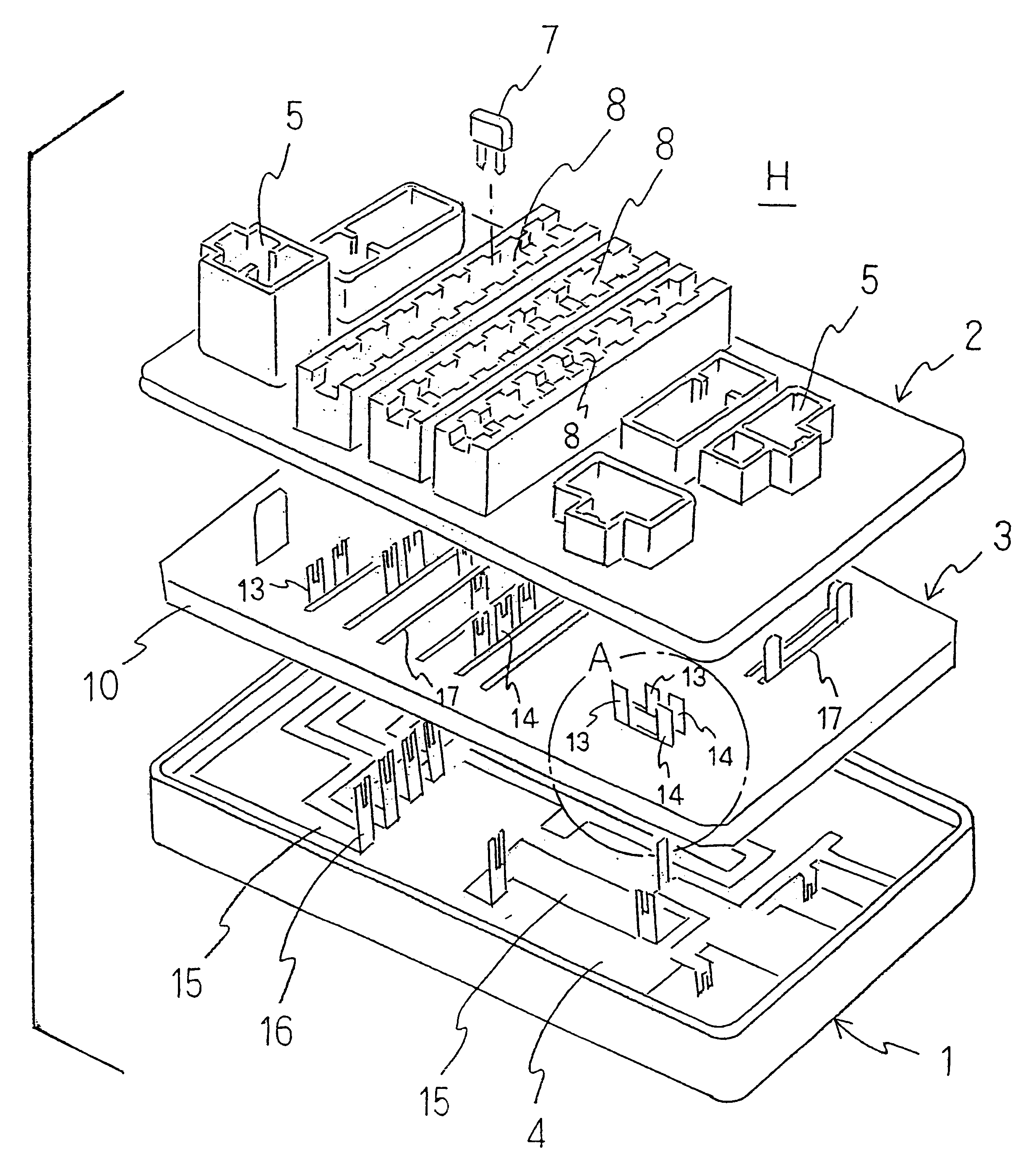
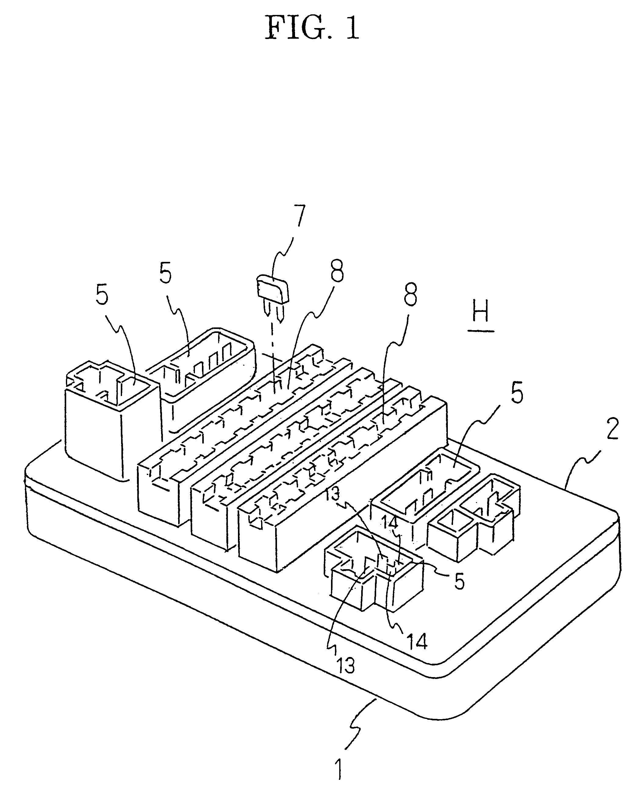
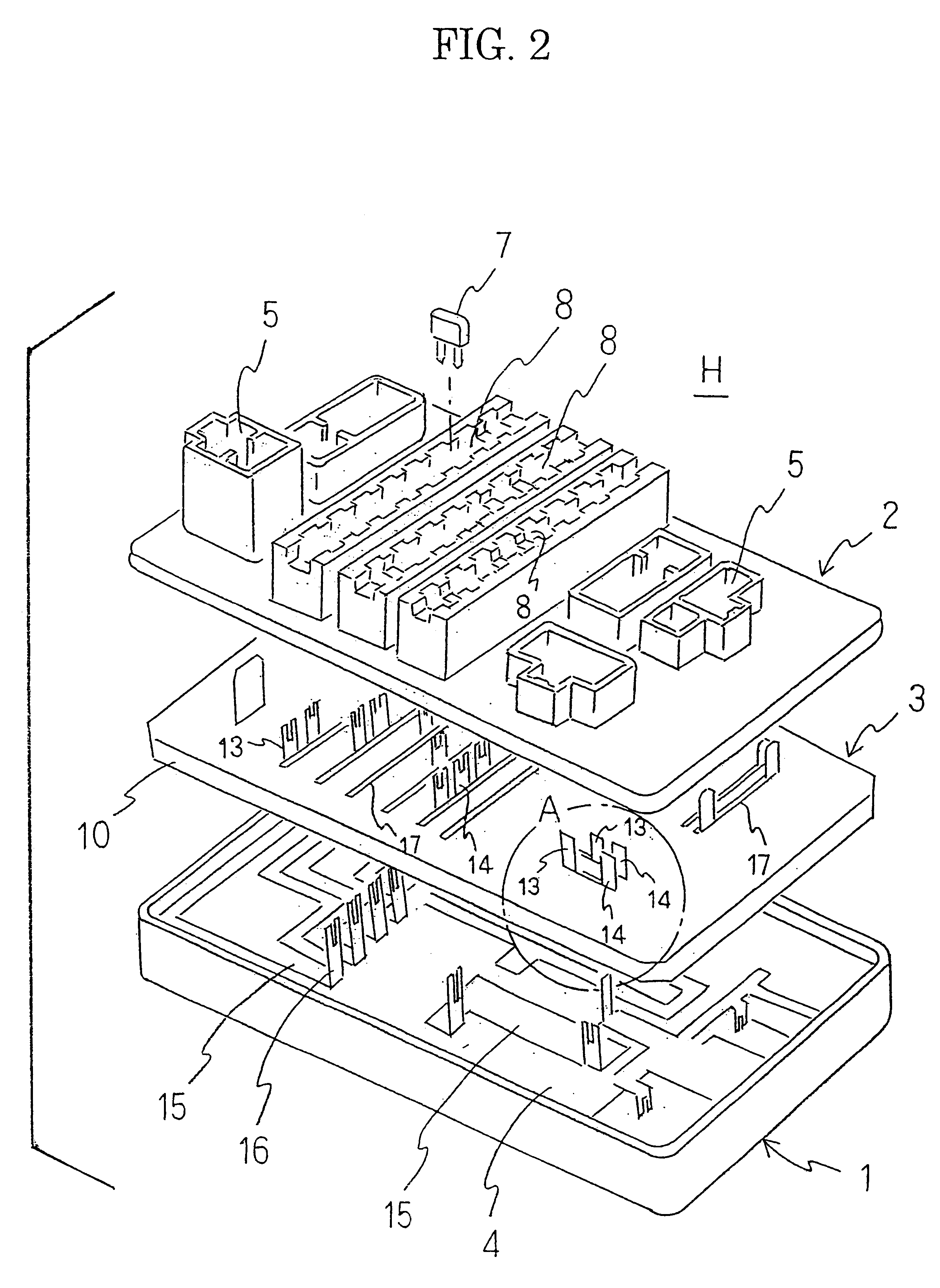
A fuse relay junction block H comprises a box body 1, a box cover 2 and a multilayered board 3 (see FIG. 2). The box body 1 has a board 4 housed therein and the box cover 2 has connection ports 5 for wirings from electrical wiring systems protruded therefrom and a plurality of mounting ports 8 for fuses 7 arranged thereon. Terminals 13, 14 of wiring members 11, 12 provided on the multilayered board 3 directly protrude into the connection ports 5 (see FIG. 1), and terminals 16 of wiring members 15 provided on the board 4 protrude into slits 17 provided on the multilayer wiring board 3, thereby assembling the fuse relay junction block H (see FIG. 1).

The multilayer wiring board 3 forming the principal part of the invention is covered with a secondary molded portion 10 (see FIGS. 4 and 5) for inserting a network structure 9 (FIG. 3) and it comprises two layers alt...


PUM


Abstract

There is provided a fuse relay junction block for use in automobiles capable of not only considerably reducing the number of assembling process but also realizing small sized, lightweight compact block, thereby enhancing reliability and achieving a low cost material by aggregating the conventional plural pieces of boards to form a multilayered circuit structure. The fuse relay junction block comprises a box cover having a plurality of connection ports through which wirings of electronic wiring systems are connected to terminals of wiring members and a plurality of filling ports for fuses, a box body engaged in the box cover, a multilayered board housed between the box cover and the box body, wherein said wiring members being arranged on not less than two layers of board and integrated with primary molded portions by insert molding to form a network structure, said network structure is subjected to an insert to form a secondary molded portion.

Description

1. Field of the InventionThe invention relates to a fuse relay junction block for use in automobiles to concentratedly control electric circuits of a variety of systems in the automobiles.2. Related ArtThere has been increasing a tendency that electronic devices or electric parts are mounted on automobiles to enhance fuel economy, anti-pollution measure, drivability, comfortableness in an interior space or the like. Electric wiring systems for driving the electric parts, electronic devices are complex in an engine room or in a car. Further, there has been considerably increasing a tendency that line brakes such as fuses, relays that are used for protecting these electric parts and electronic devices from overcurrent thereof.Fuse relay junction blocks (that is also called a fuse relay control box, a fuse relay box or a fuse relay box) are divided into and installed on two blocks of an interior electrical wiring system and an engine room electrical wiring system, and wiring systems am...

Claims


Application Information

Patent Timeline
IPC IPC(8): H01L23/58H01L23/62H01R9/24H05K3/20H01R43/24H01R43/20H05K3/46H05K1/00H05K3/00
CPCH01L23/62H01R9/2466H05K3/202H01H2085/208H01R43/24H01R2201/26H05K1/0298H05K3/0014H05K3/4685H05K2201/09118H05K2201/0969H05K2203/1476Y10S439/949H01L2924/0002H01L2924/00
Inventor KOSHIBA, KIYOFUMI
Owner KOHJIN CO LTD
Learn More