Infrared/visible energy protection for millimeter wave bolometer antenna method and apparatus

a bolometer and infrared/visible technology, applied in the field of electromagnetic wave sensors, can solve the problems of difficult for a mmw bolometer antenna array sensor to discriminate between mmw energy and mmw energy, and the bolometer is sensitive to any source of heat,

Inactive Publication Date: 2002-08-27
RAYTHEON CO
View PDF1 Cites 51 Cited by
  • Summary
  • Abstract
  • Description
  • Claims
  • Application Information

AI Technical Summary

Problems solved by technology

One disadvantage of this present MMW imaging technology is that bolometers are sensitive to any source of heat.
While there are a number of thermal considerations in the foregoing design to control the affects of other heat sources, such as thermal isolation and thermal stabilization, some sources of heat energy are not readily controllable.
It is therefore difficult for a MMW bolometer antenna array sensor to discriminate between MMW e

Method used


Image

  • Infrared/visible energy protection for millimeter wave bolometer antenna method and apparatus
  • Infrared/visible energy protection for millimeter wave bolometer antenna method and apparatus
  • Infrared/visible energy protection for millimeter wave bolometer antenna method and apparatus

Examples


Embodiment Construction

Illustrative embodiments and exemplary applications will now be described with reference to the accompanying drawings to disclose the advantageous teachings of the present invention. While the present invention is described herein with reference to illustrative embodiments for particular applications, it should be understood that the invention is not limited thereto. Those having ordinary skill in the art and access to the teachings provided herein will recognize additional modifications, applications, and embodiments within the scope thereof and additional fields in which the present invention would be of significant utility.

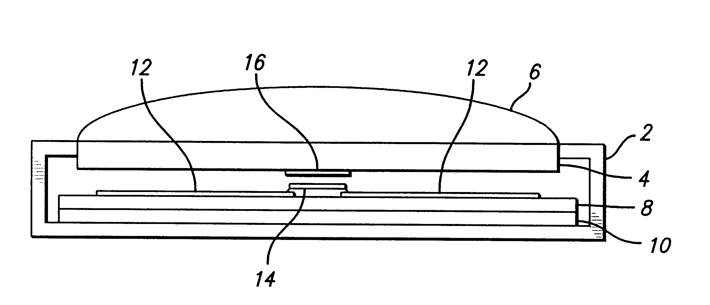
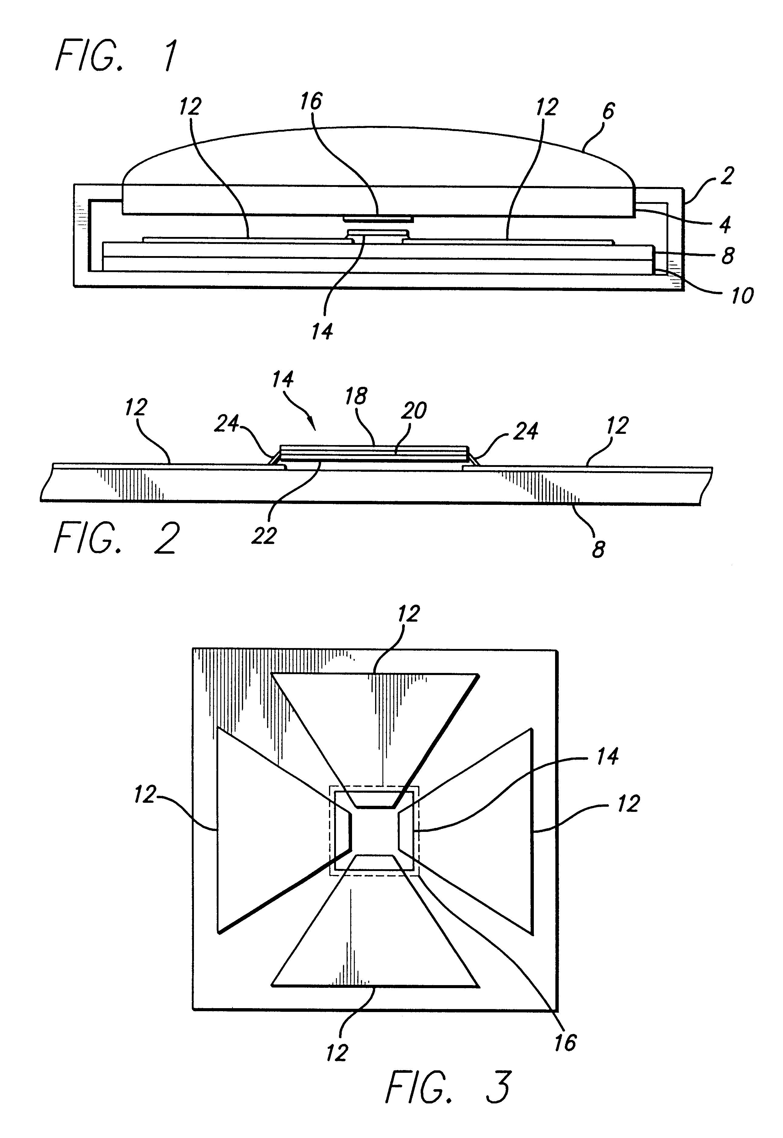
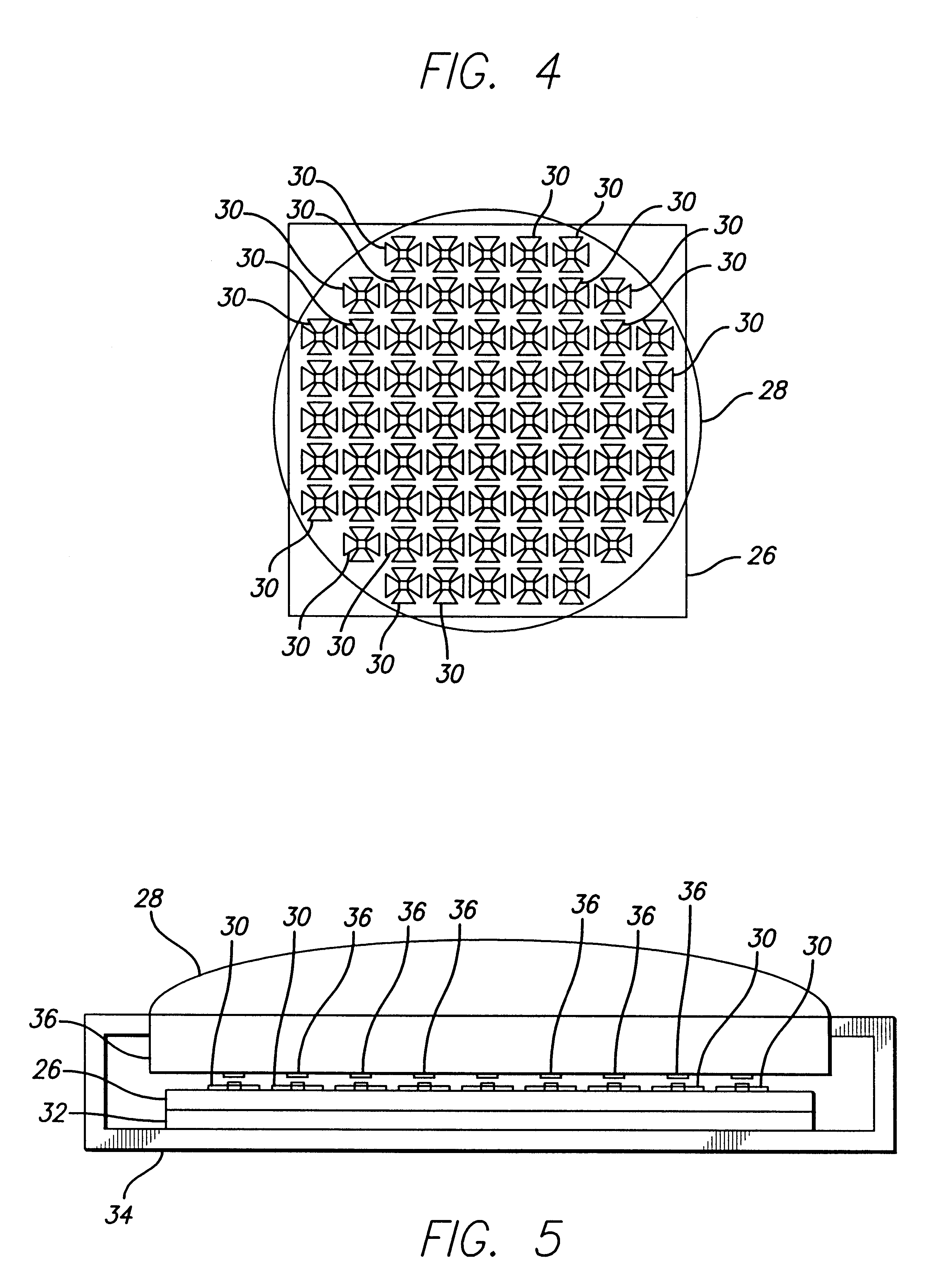
An illustrative embodiment of the present invention is a millimeter wave (MMW) imaging sensor that utilizes a focal plane array of MMW sensors to form an image of energy incident on the sensor in the MMW band. It is understood by those skilled in that art that windows of atmospheric transmission exist in the MMW band at approximately 95 GHz, 140 GHz, 220 GHz, a...


PUM


Abstract

A method and apparatus for protecting a bolometer antenna imaging array from out of band electromagnetic energy is disclosed. Protective pads are disposed upon a window in an optical system forming a millimeter wave image on an array of bolometer antenna sensors. The protective pads are effectively opaque to infrared and visible emissions and are aligned to shade the bolometer portion of the bolometer antennas from infrared and visible emissions, while leaving the antenna portion of each sensor in the array exposed to intercept the millimeter wave energy incident upon them.

Description

1. Field of the InventionThe present invention relates to electromagnetic wave sensors. More specifically, the present invention relates to systems and methods for protecting millimeter wave imaging arrays from infrared and visible light emissions.2. Description of the Related ArtMillimeter wave (MMW) frequency bands lie in the range from approximately 30 GHz to over one terahertz. This band of frequencies is of particular interest in imaging applications because atmospheric `windows` exists through which certain bands of MMW frequencies pass with low attenuation. In particular, the bands near 95 GHz, 140 GHz, 220 GHz, and 330 GHz exhibit low attenuation characteristics even in the presence of air, clouds, fog, rain, and other precipitation. This affords an option for imaging where other frequencies, such as visible spectrum and infrared, are attenuated to such a severe degree that imaging is not practicable. Applications in aerospace, military and commercial exists which gain signi...

Claims


Application Information

Patent Timeline
IPC IPC(8): G01J5/08G01J5/20
CPCG01J5/08G01J5/0806G01J5/0837G01J5/0884H01Q1/42G01J2005/202
Inventor GRINBERG, JANJACK, MICHAEL D.
Owner RAYTHEON CO
Why Eureka
Try Eureka