Optical packet exchange system and optical switch

a packet exchange system and optical switch technology, applied in data switching networks, multiplex communication, digital transmission, etc., can solve the problem of being unable to control the exchange apparatus at a high speed

Inactive Publication Date: 2002-08-27
NEC CORP
View PDF11 Cites 24 Cited by
  • Summary
  • Abstract
  • Description
  • Claims
  • Application Information

AI Technical Summary

Benefits of technology

In view of the above-described problems, it is a primary object of the present invention to eliminate any of the aforementioned problems. Particularly, it is an object of the present invention to provide an optical packet exchange apparatus and an optical switch in which searching for connection patterns between input units devoid of packet(s) for transmission and output units devoid of packet(s) for reception is reduced and can be performed speedily. It is another object to provide an optical packet exchange apparatus and an optical switch in which, if the number of channels of the exchange apparatus is increased or the network speed is higher, switch control can be made quickly to suppress or reduce the hardware scale.

Problems solved by technology

If the network speed is increased, it becomes impossible to control the exchange apparatus at a high speed.

Method used


Image

  • Optical packet exchange system and optical switch
  • Optical packet exchange system and optical switch
  • Optical packet exchange system and optical switch

Examples


example 1

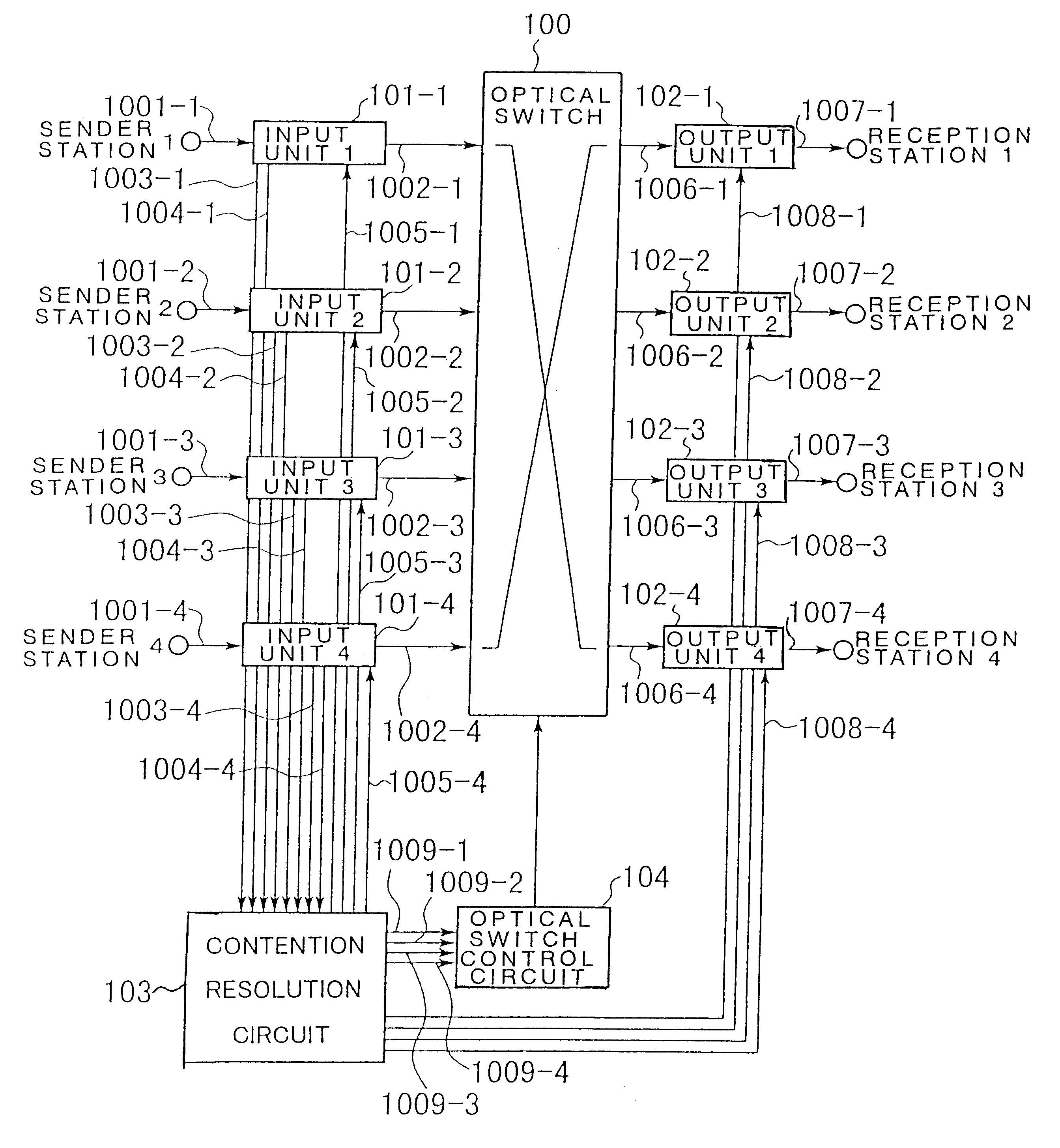
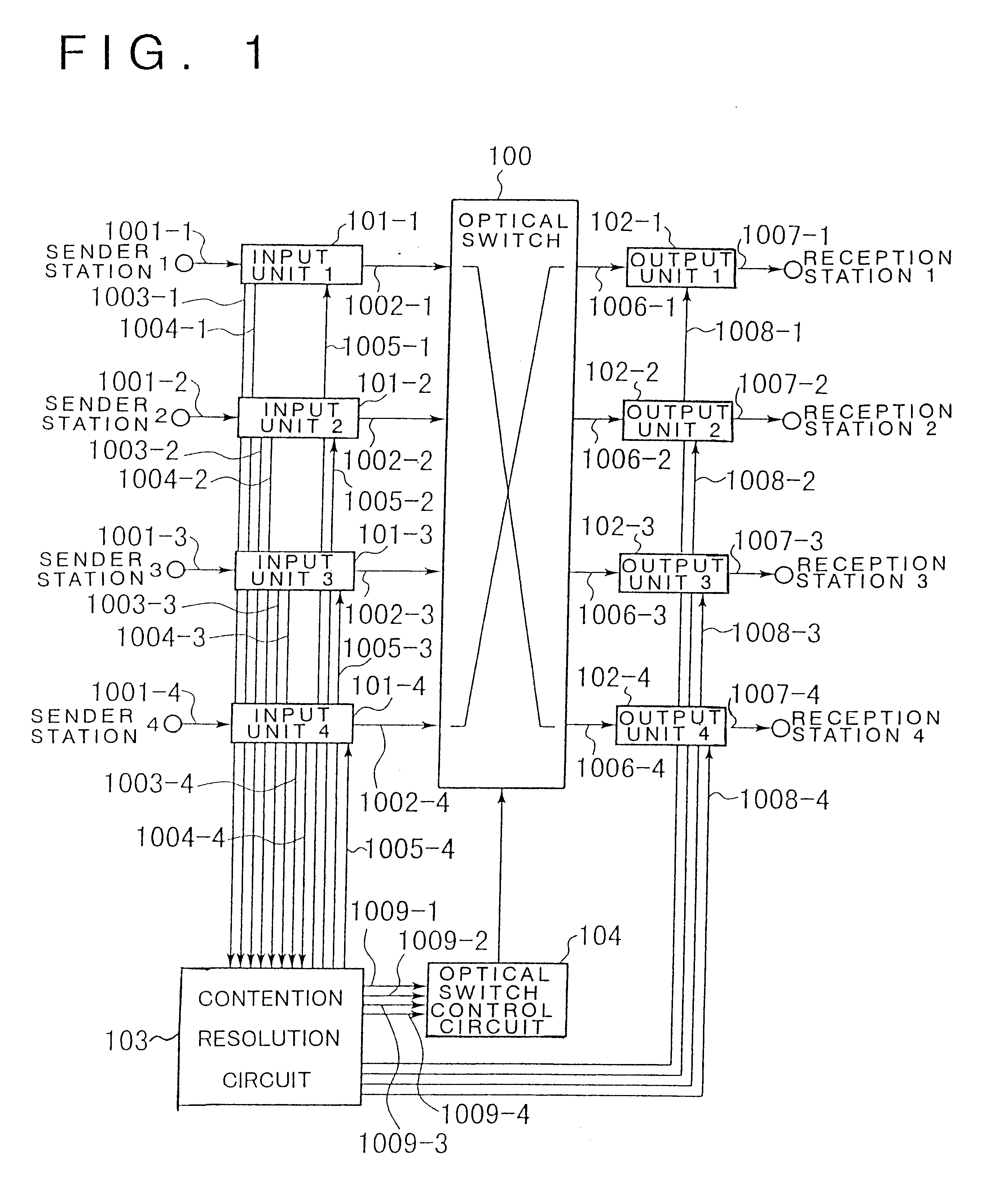
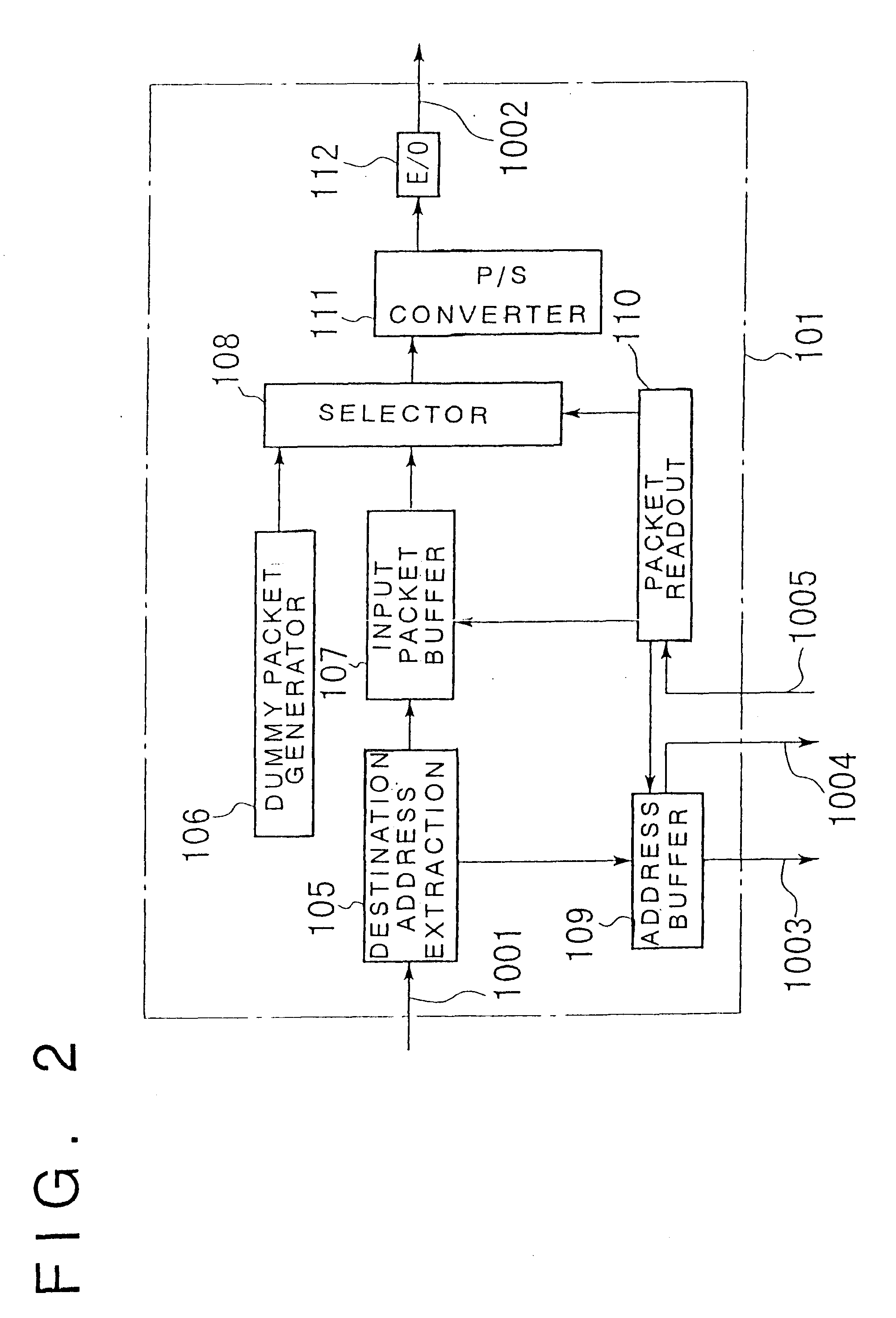
A first example of the present invention will be explained with reference to FIGS. 1 to 4, 24, 25 and 37. FIG. 1 shows the configuration of the first example of the present invention. The pre-set example is an optical packet exchange apparatus in which the second aspect of the invention is applied to the first aspect of the invention and comprised of the input side of four channels and the reception side of four channels. Referring to FIG. 1, the optical packet exchange apparatus includes four input units 101, an optical switch 100, four output units 102, a contention resolution circuit 103, and an optical switch control circuit 104.

FIG. 37 shows an illustrative structure of an optical switch 100. Referring to FIG. 37, the optical switch 100 is a splitter / combiner type optical switch of four input channels and four output channels comprised of four optical splitters 10, 16 optical gates 11 and four optical combiners 12. The optical gate 11 is a semiconductor light amplifier which, u...

example 2

Referring to FIGS. 3 to 7, a second example is explained. FIG. 5 shows the structure of the second example. This example is directed to an optical packet exchange apparatus for the 4 transmission channels and 4 reception channels practicing the fourth aspect of the present invention. Referring to FIG. 5, the packet exchange apparatus is comprised of four input units 201, an optical switch 100, four output units 202, a contention resolution circuit 103, an optical switch control circuit 104 and a dummy packet input unit 222.

First, the operation of the optical packet exchange apparatus of the second example in its entirety is explained with reference to FIG. 5.

Transmission packets, sent from the sending station, are buffered at the input units 201. The input units 201 each send a destination address 1003 of the transmission packet and a connection request signal to the contention resolution circuit 103. The contention resolution circuit 103 receives the destination addresses 1003-1 to...

example 3

Referring to FIGS. 8 and 10, a third example is explained. FIG. 8 shows the structure of the third example. This example is directed to an optical packet exchange apparatus for the 4 transmission channels and 4 reception channels practicing the fifth aspect of the present invention to which the sixth and eighth aspects of the invention have been applied. Referring to FIG. 8, the packet exchange apparatus is comprised of four input units 101, an optical switch 100, four output units 302, a contention resolution circuit 103, and an optical switch control circuit 104.

First, the operation of the optical packet exchange apparatus of the third example in its entirety is explained with reference to FIG. 8.

Referring to FIG. 8, the transmission packet, sent from the sending station, is buffered at the input unit 101. The input unit 101 sends a destination address 1003 of the transmission packet and a connection request signal 1004 to the contention resolution circuit 103. The contention reso...


PUM


Abstract

An optical packet exchange apparatus and an optical switch in which search for a connection pattern between an input unit devoid of a packet to be transmitted and an output unit devoid of a packet to be received is reduced to enable fast switch control even in cases wherein the number of channels of the exchange apparatus is increased or network speed is higher. A plurality of input units, a plurality of output units and an optical switch are provided. Each input unit includes an input buffer unit, a parallel / serial conversion unit, an electrical / optical conversion unit, and a dummy packet insertion unit for sending a dummy packet if there is no packet to be transmitted. Each output unit includes an exchange counterpart contention resolution unit for controlling the exchange counterpart, an optical / electrical conversion unit, a serial / parallel conversion unit, and a packet eliminating unit. The exchange counterpart contention resolution unit controls the packet eliminating unit to eliminate a dummy packet.

Description

This invention relates to a packet exchange apparatus. More particularly, it relates to a broad-band optical packet exchange apparatus employing an inexpensive optical / electrical converter.In a packet exchange apparatus employing an optical switch in an exchange stage and also employing an electrical / optical converter and an optical / electrical converter in an input / output unit, the optical / electrical converter is usually of an ac coupling circuit configuration. In this case, there is presented a problem that, if there is any time period during which the 1 or 0 level continues for a longer time than a pre-set time period or during which there is no packet to be received, data dropout occurs in the packet or in the directly following packet.As a method for overcoming this problem, there is proposed in, for example, JP Patent Kokai JP-A-4-72939 a packet exchange apparatus employing an optical switch in which a dummy data appending circuit is provided on the transmission side so that du...

Claims


Application Information

Patent Timeline
Patent Type & Authority Patents(United States)
IPC IPC(8): H04L12/56H04Q11/00H04B10/27H04B10/00H04L12/931H04Q3/00H04Q3/52
CPCH04L49/30H04L49/50H04Q11/0001H04L49/25H04Q2011/0024H04Q2011/0039H04Q2011/0045H04Q2011/005
Inventor ARAKI, SOICHIROSUEMURA, YOSHIHIKOTAJIMA, AKIOTAKAHASHI, SEIGOMAENO, YOSHIHARUHENMI, NAOYA
Owner NEC CORP
Why Eureka
Try Eureka